D-8
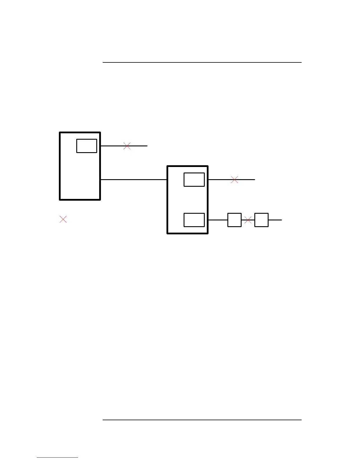
The illustration below shows a MINIPLEX system with one transponder that has three
earth faults:
• SPS NAC on the SPS in the Main Panel
• RPS AUXPWR output on the RPS in Transponder 1
• IDNet channel in Transponder 1
Transponder
1
Main
Panel
RUI
SPS
NAC 2
RPS
AUXPWR
Iso
1
Iso
2
= Ground Fault
RPS
SPS
IDNet
IDNet
Channel
M2
Figure F-1. Earth Fault Example
The panel reports two earth faults—one for each power supply. The third fault is as yet
unreported.
The example below shows the progression of events in finding and repairing the three
faults. They are presented as instructions to a technician who does not yet know about the
third fault.
A. Find and repair the fault in the main panel.
1. After opening the Earth Fault Search diagnostic menu option, select Location
Search.
9. Select the SPS located in the Main Panel (this selects the Main Panel as the
location for the search).
10. When prompted, select exclusion of AUXPWR circuits.
11. Start the search. (The panel turns on the earth fault search trouble pseudo-point
and the keypad inactivity utility pseudo-point to disable timeout during the
search).
12. The search completes. The panel indicates that NAC 2 on the SPS has the earth
fault. All slaves are reset (and the panel turns off the earth fault search trouble
pseudo-point).
13. Repair the earth fault on NAC 2. When this is done, the trouble from the SPS
clears but the trouble from the RPS is still indicated.
Continued on next page
Earth Fault Search Example