EasyManuals Logo

Simplex 4100U Installation & Maintenance

Simplex 4100U
180 pages
To Next Page IconTo Next Page
To Previous Page IconTo Previous Page
Page #68 background imageLoading...
Page #68 background image
3-40
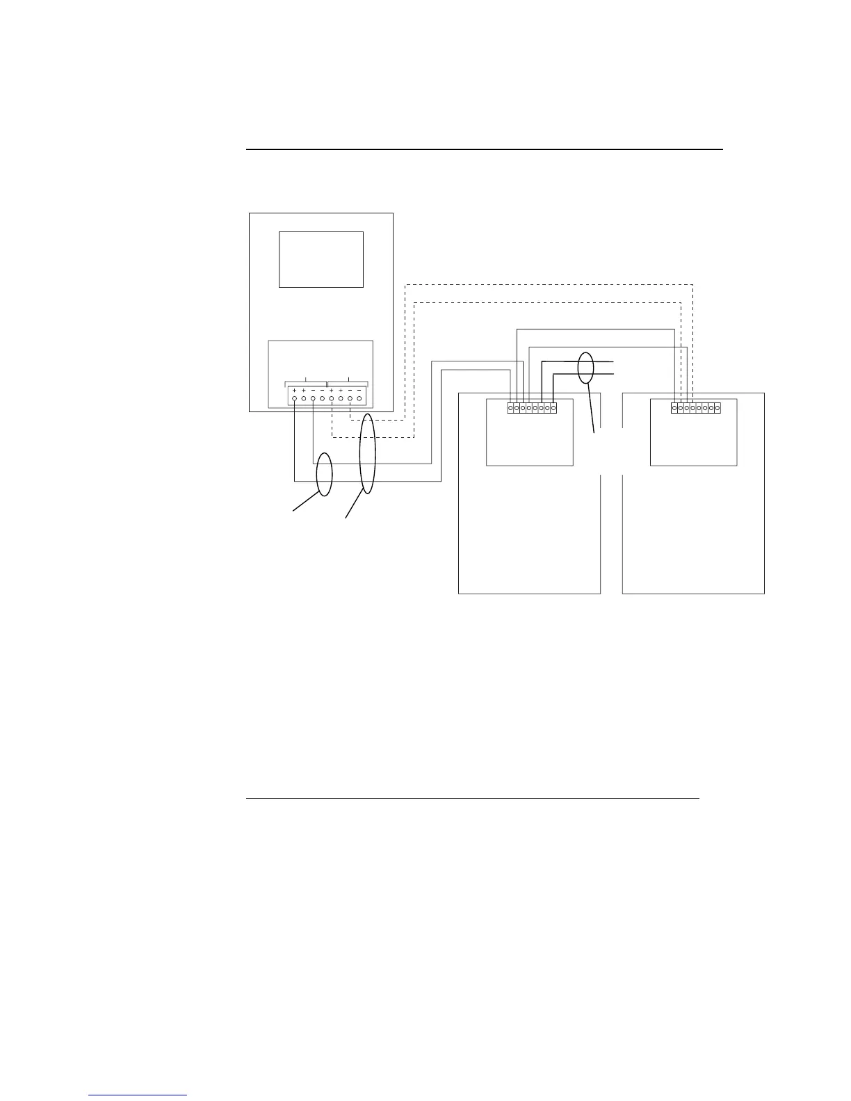
The illustration below applies to Class A and Class B wiring.
4100 MINIPLEX MASTER
RIC 11
565-233
MINIPLEX
TRANSPONDER
562-856 W/565-217
COMMS "A"
81
COMMS "B"
RUI
T
B
1
T
B
1
RIC 11
565-233
MINIPLEX
TRANSPONDER
81
T
B
1
Figure 3-7. MINIPLEX Wiring
Notes:
1. Power wiring is not shown. Connect the RIC II card to the UPS or expansion
power supply in the transponder cabinet.
2. If a UPS is not provided in the transponder cabinet, then 24 V must be
provided from the host panel.
3. Maintain correct polarity on terminal connections. Do not loop wires under
terminals.
4. All wiring is supervised and power limited.
MINIPLEX Wiring (Non-4100U), Continued
Wiring Illustration
CLASS A
CLASS B
+24 V
24 C
See
Note 1
II II

Table of Contents

Other manuals for Simplex 4100U

Questions and Answers:

Question and Answer IconNeed help?

Do you have a question about the Simplex 4100U and is the answer not in the manual?

Simplex 4100U Specifications

General IconGeneral
Control Panel TypeAddressable Fire Alarm Control Panel
DisplayLCD
Power Supply120/240 VAC, 50/60 Hz
Max Signaling Line Circuits (SLC)2
Operating Temperature0°C to 49°C (32°F to 120°F)
Humidity Range10% to 93% non-condensing
Network CapabilityYes
Communication ProtocolRS-232, RS-485
Battery Backup24 VDC
NAC Outputs4
Signaling Line Circuits (SLCs)2
Power Supply Current3.0 A
Max Notification Appliance Circuits (NAC)4
Max Releasing Circuits4
Max Relay Circuits4
Communication PortsRS-232, RS-485

Related product manuals