EasyManuals Logo

Simplex 4100U Installation & Maintenance

Simplex 4100U
180 pages
To Next Page IconTo Next Page
To Previous Page IconTo Previous Page
Page #53 background imageLoading...
Page #53 background image
2-25
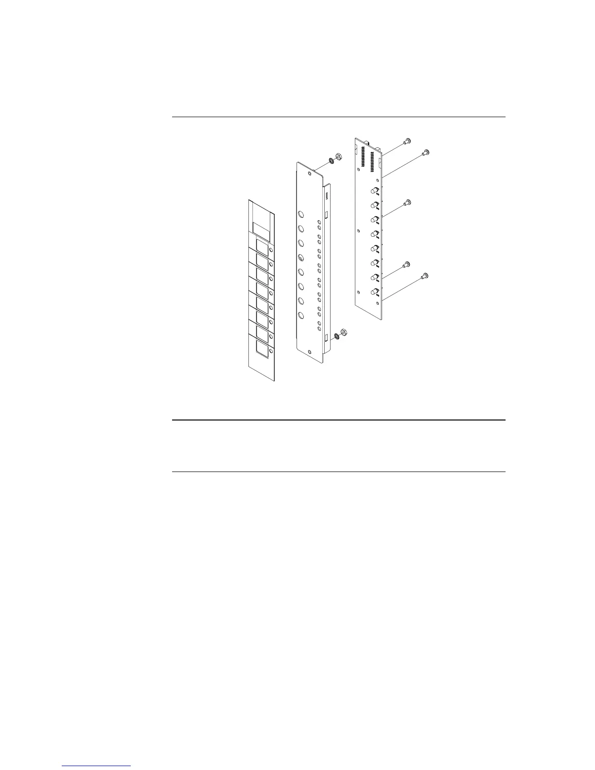
Figure 2-18. Assembling / Disassembling the LED Display Card
User interface wiring consists of connecting the LED/switch controller card to the
expansion bay’s power distribution interface (PDI), and connecting display cards to each
other. This section describes both procedures.
Continued on next page
Step 6. Installing LED/Switch Modules into Expansion Bays (4100U),
Continued
Changing Display
Card LEDs,
(continued)
Interconnecting
Cards

Table of Contents

Other manuals for Simplex 4100U

Questions and Answers:

Question and Answer IconNeed help?

Do you have a question about the Simplex 4100U and is the answer not in the manual?

Simplex 4100U Specifications

General IconGeneral
Control Panel TypeAddressable Fire Alarm Control Panel
DisplayLCD
Power Supply120/240 VAC, 50/60 Hz
Max Signaling Line Circuits (SLC)2
Operating Temperature0°C to 49°C (32°F to 120°F)
Humidity Range10% to 93% non-condensing
Network CapabilityYes
Communication ProtocolRS-232, RS-485
Battery Backup24 VDC
NAC Outputs4
Signaling Line Circuits (SLCs)2
Power Supply Current3.0 A
Max Notification Appliance Circuits (NAC)4
Max Releasing Circuits4
Max Relay Circuits4
Communication PortsRS-232, RS-485

Related product manuals