2-7
In the USA, a number of variants of power supply are available, e.g. SPS, RPS, XPS,
XCharger each with different portions of circuitry (eg NACs, Battery Charger, IDNet)
fitted or not fitted. In Australia, only one variant (SPS) is currently available, and it has
hardware and software that are specific to Australia. This unit is used as the main power
supply, but may also be fitted directly to a card bay as an expansion supply.
The system power supply (SPS) is mains powered and has backup batteries that get
switched in on mains failure. It is the initial power source for the CPU and the host
cabinet. The SPS provides 24V card power to the CPU motherboard and the other cards.
It also supplies 24V power on a separate bus to the outputs, e.g. Notification Appliance
Circuits (NACs).
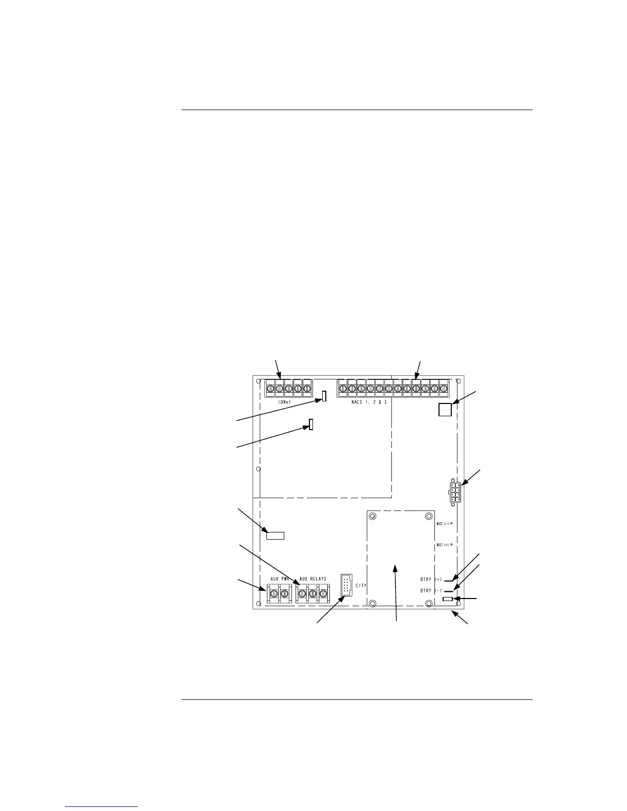
The SPS also has three on-board NACs that support reverse polarity supervision. It
provides an IDNet channel, auxiliary power, an auxiliary relay, and it mounts and drives
the Alarm Relay Card.
The SPS performs functions such as brownout detect, battery transfer, battery recharge,
earth fault detection, and power limiting of outputs. It provides voltage and current
information to the CPU card, which can then be displayed at the user interface.
Figure 2-4. System Power Supply
Continued on next page
Introduction to FACPs (4100U), Continued
System Power
Supply (SPS)
CITY / RELAY CARD
MOUNTING AREA
CITY CARD
CONNECTOR (P7)
AUXILIARY RELA