EasyManuals Logo

Simplex 4100U Installation & Maintenance

Simplex 4100U
180 pages
To Next Page IconTo Next Page
To Previous Page IconTo Previous Page
Page #121 background imageLoading...
Page #121 background image
7-13
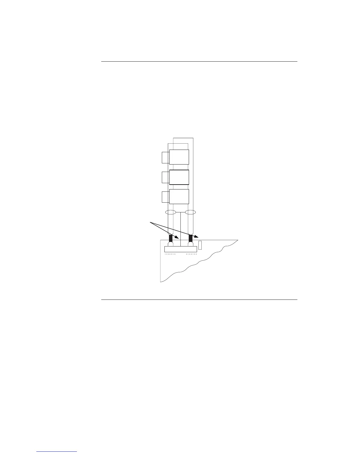
To connect addressable devices/detectors to the SPS IDNet using Class A wiring, read the
following instructions.
1. Ferrite beads are required on the SPS IDNet cables (ref Fig 7.1).
2. Route wire (between 0.75 mm
2
and 4 mm
2
) from the B+, B- outputs on TB1 of
the SPS to the appropriate inputs on a peripheral IDNet device.
3. Route wire from the first IDNet device to the next one. Repeat for each device.
4. Route wire from the last IDNet device to the A+ and A- inputs on TB1 of the
SPS.
B+ B- SHLD
IDNet
A+
P1
3
2
1
A-
IDNet
DEVICE
IDNet
DEVICE
IDNet
DEVICE
IDNet LOOP
(CLASS A / STYLE G)
Figure 7-6. Class A Wiring
Continued on next page
SPS IDNet Wiring, Continued
Class A Wiring
IDNet
DEVICE
IDNet
DEVICE
IDNet
DEVICE
Ferrite beads
required.

Table of Contents

Other manuals for Simplex 4100U

Questions and Answers:

Question and Answer IconNeed help?

Do you have a question about the Simplex 4100U and is the answer not in the manual?

Simplex 4100U Specifications

General IconGeneral
Control Panel TypeAddressable Fire Alarm Control Panel
DisplayLCD
Power Supply120/240 VAC, 50/60 Hz
Max Signaling Line Circuits (SLC)2
Operating Temperature0°C to 49°C (32°F to 120°F)
Humidity Range10% to 93% non-condensing
Network CapabilityYes
Communication ProtocolRS-232, RS-485
Battery Backup24 VDC
NAC Outputs4
Signaling Line Circuits (SLCs)2
Power Supply Current3.0 A
Max Notification Appliance Circuits (NAC)4
Max Releasing Circuits4
Max Relay Circuits4
Communication PortsRS-232, RS-485

Related product manuals