7-4
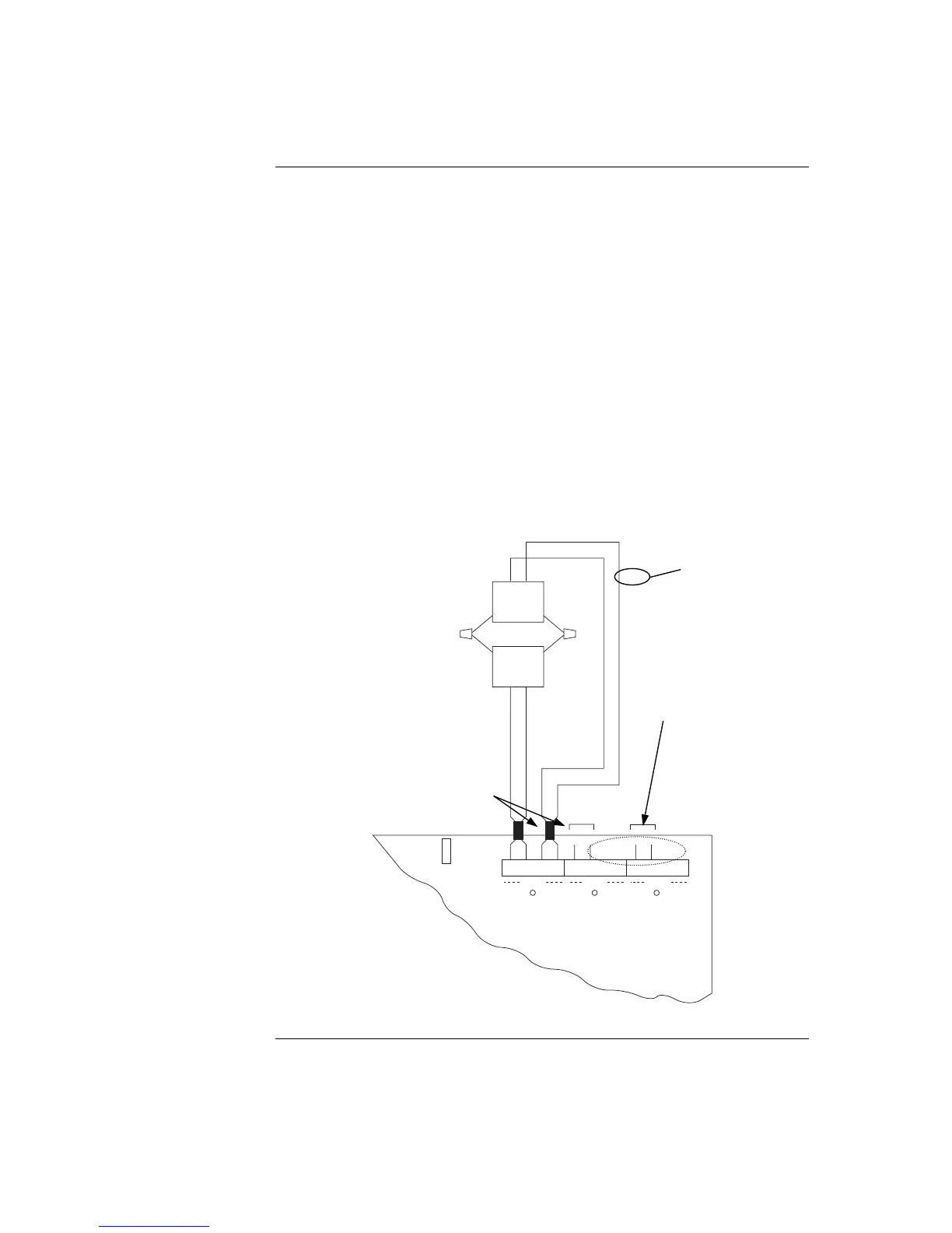
To connect the SPS to reverse-polarity, non-addressable notification appliances using
Class A wiring, read the following instructions and refer to the figure below.
1. Route wire (between 0.75 mm
2
and 4 mm
2
) from the “B+”, “B-”, outputs on TB2
of the SPS to the appropriate inputs on a peripheral notification appliance. Use
NAC1, NAC2, or NAC3 as configured..
2. Route wire from the first appliance to the next one. Repeat for each appliance.
3. Route wire from the last appliance to the A+ and A- inputs on the same NAC
circuit of TB1 of the SPS.
4. Repeat steps 1 through 3 for each NAC output you want to use.
5. Leave the 10 K, ½ W, brown/black/orange resistor (378-030) on each the “B+”
to “B-” terminals of each unused NAC. No external end-of-line resistor is
needed for circuits in use.
6. If the appliance/device to be used does not have an integral diode, a sufficiently
rated blocking diode must be fitted between the incoming +ve wire and the +ve
terminals of the device with cathode to the device.
P1
3
2
1
B+ B- A+ A-
TYPICAL
APPLIANCE
RED
RED
RED
NAC1
B+ B- A+ A-
NAC1
B+ B- A+ A-
NAC1
LED1 LED2 LED3
TYPICAL
APPLIANCE
BLK
BLK
BLK
NAC2
NAC3
Figure 7-2. Class A NAC Wiring
Continued on next page
SPS NAC Field Wiring Guidelines, Continued
Class A NAC Wiring
SPS NAC Field Wiring Guidelines, Continued
0.75 mm