2-16
• Motherboards can be installed on top of the PDI in expansion bays. The data and
power that would normally be bussed via the PDI is instead routed across the boards
via ribbon cable from one board to the next.
• Up to eight 2” (51 mm) x 11 ½” (292 mm) motherboards can be installed in an
expansion bay if no 4”x 5”modules are installed in the bay, and if the pins on the
left connector (usually P1) on the leftmost motherboard are removed.
Motherboards are mounted on top of the PDI in expansion bays. The data and power
that would normally be bussed via the PDI is instead routed across the boards via
ribbon cable from one board to the next.
• Motherboards should be added from left to right.
• Relay motherboards must be the rightmost motherboards.
• In the first bay of an FACP, the CPU motherboard is the right most motherboard, and
other motherboards are fitted to its left side.
• The CPU motherboard generates the 8V supply required for 4100A motherboards. It
also has the 4100A style Molex connectors to which a harness can be fitted as per Fig
2-8.
Power Distribution
Interface
4100 Option Bd
4100 Option Bd
4100 Option Bd
4100 Option Bd
4100 Option Bd
4100 Option Bd
4100 Option Bd
Slot 2 Slot 3 Slot 4 Slot 5 Slot 6 Slot 7 Slot 8Slot 1
This Slot
Must
Remain
Empty
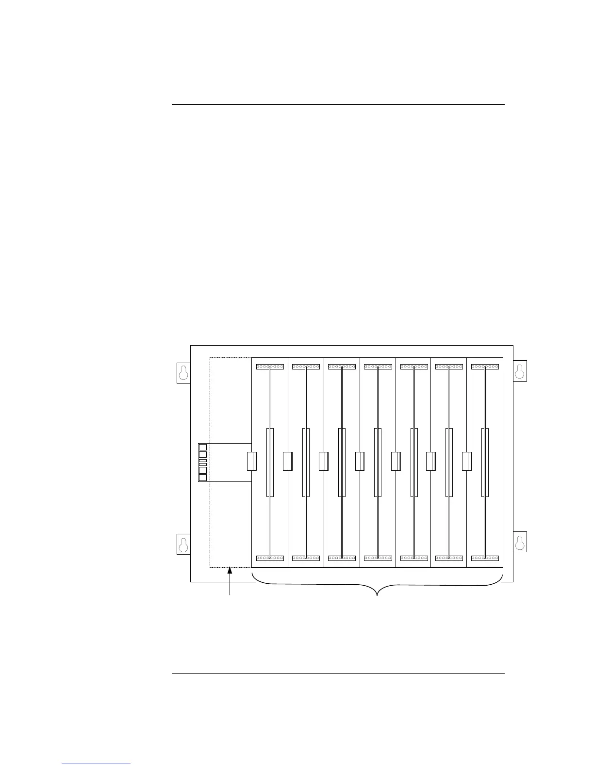
Figure 2-10. Expansion Bay Motherboard Placement
Continued on next page
Step 5. Installing Modules into Expansion Bays (4100U), Continued
Placement
Guidelines
(continued)
This slot cannot contain a
motherboard unless the pins
on P1 (or leftmost pin
connector) are removed.
Up to eight 2” (51mm) x 11 ½” (292 mm) motherboards can be
mounted in an expansion bay. Seven motherboards fit into Slots
2 through 8; the eighth can be added in Slot 1 if its leftpost pins
are removed.