EasyManuals Logo

Simplex 4100U Installation & Maintenance

Simplex 4100U
180 pages
To Next Page IconTo Next Page
To Previous Page IconTo Previous Page
Page #54 background imageLoading...
Page #54 background image
2-26
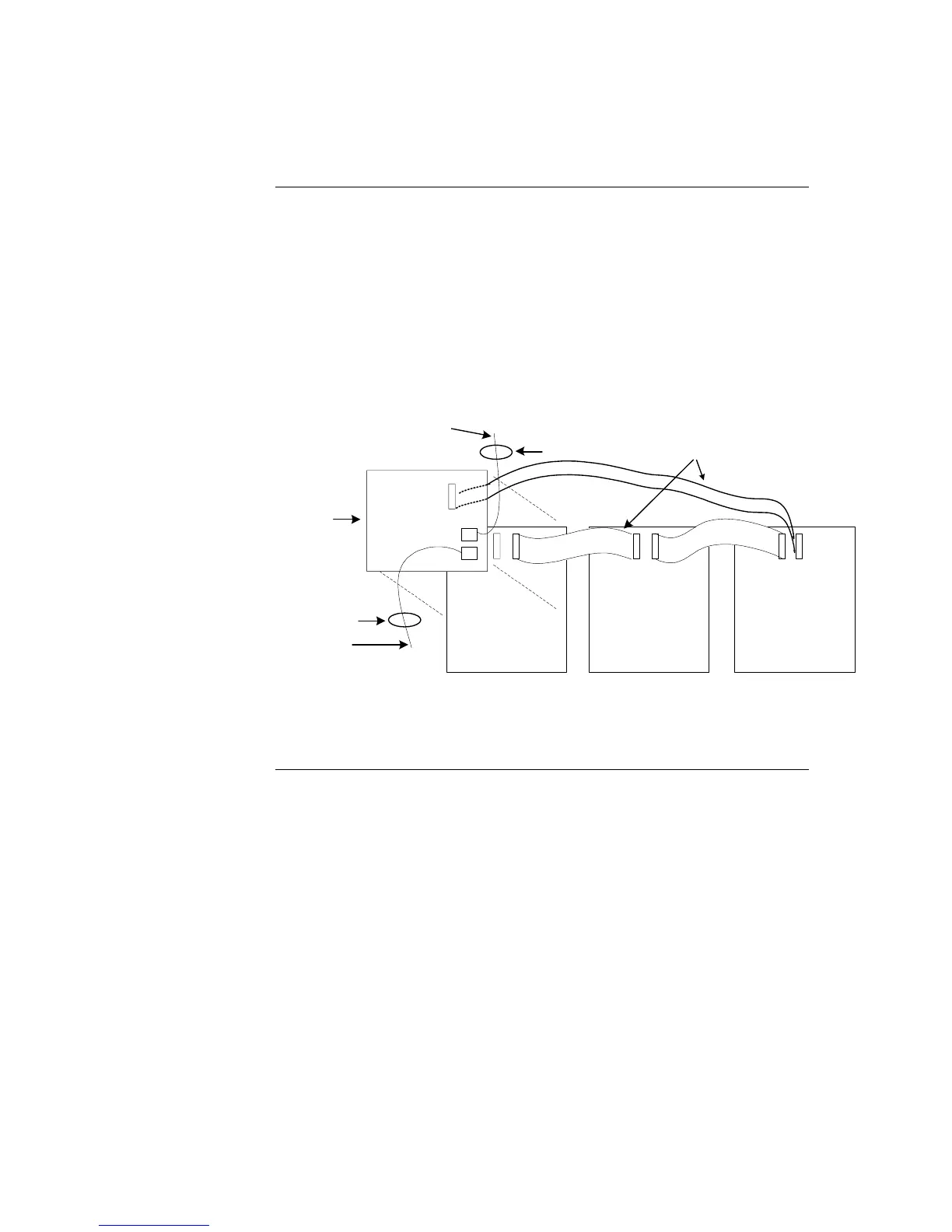
The following directions are complete instructions on interconnecting display cards and
connecting the controller card to a power source.
1. Use Harness 734-008 to connect P2 on the controller card to one of the 4-pin
connectors on the PDI.
2. If there are multiple controller cards, use Harness 734-036 to connect P3 on the
controller card to P2 on another controller card.
3. Interconnect all LED/switch display cards with the ribbon cables (provided).
Connector P1 is the input; connector P2 is the output.
TO PDI CONNECTOR OR ANOTHER
CONTROLLER CARD
P4
(reverse side)
HARNESS 734- 036
LED / SWITCH
CONTROLLER
26 - CONDUCTOR
RIBBON CABLE
LED/ SWITCH
MODULE 3
LED/ SWITCH
MODULE 2
LED/ SWITCH
MODULE 1
TO ANOTHER
CONTROLLER CARD
HARNESS 734 008
IN
OUT IN
OUT IN
Figure 2-19. LED/Switch Controller Wiring
Step 6. Installing LED/Switch Modules into Expansion Bays (4100U),
Continued
Wiring Instructions

Table of Contents

Other manuals for Simplex 4100U

Questions and Answers:

Question and Answer IconNeed help?

Do you have a question about the Simplex 4100U and is the answer not in the manual?

Simplex 4100U Specifications

General IconGeneral
Control Panel TypeAddressable Fire Alarm Control Panel
DisplayLCD
Power Supply120/240 VAC, 50/60 Hz
Max Signaling Line Circuits (SLC)2
Operating Temperature0°C to 49°C (32°F to 120°F)
Humidity Range10% to 93% non-condensing
Network CapabilityYes
Communication ProtocolRS-232, RS-485
Battery Backup24 VDC
NAC Outputs4
Signaling Line Circuits (SLCs)2
Power Supply Current3.0 A
Max Notification Appliance Circuits (NAC)4
Max Releasing Circuits4
Max Relay Circuits4
Communication PortsRS-232, RS-485

Related product manuals