5-19
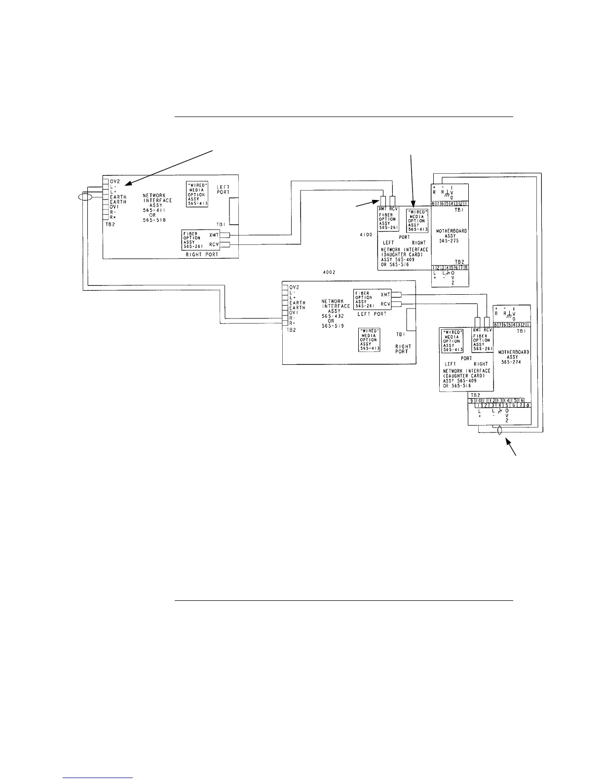
Figure 5-14. Wired Media and Fiber Optic, Style 7 Wiring
Step 4. Wiring Network Cards , Continued
Wired Media and
Fiber Optic,
Style 7 Wiring
Notes:
1. Refer to general wiring precautions in this
chapter, as well as Field Wiring Specifications:
document 900-082 for 4100; 900-242 for 4100U.
For specific information about fiber optic wiring, refer to the 900-143 Fiber Tutorial.
2. The maximum distance between nodes when using the fiber communication path is
dependent upon the fiber’s multimode graded index: 10,000 feet (3,048 m) for 50/125 fiber;
15,000 feet (4,572 m) for 62.5/125 fiber. The maximum cable O.D. is 0.118 (3 mm).
Reference document 900-143 for other fiber sizes.
3. ST connectors with long strain relief boots are to be used with the fiber optic cable.
4. On assembly 565-274, JW1 and JW2 must be installed. Jumper plugs must not be installed on P5-P8.
5. Cable clamps supplied with 748-531 are used to secure the fiber cable.
6. When the 565-413 Interface Card is used with 565-516, -407, or –409 Network Card, TB1 on the 565-413 Interface
Card cannot be used. Connection to the motherboard is required as shown.
7. The shield should only be connected at one end of the line. The shield is connected to the left port.
8. Each “wired” media cable requires two ferrite beads, one at each end (included in the shipping group). Refer to
installation instructions 574-041 for proper bead mounting.
9. When wiring leaves the building, 2081-9044 Overvoltage Protectors are required. One overvoltage protector is installed
where wiring leaves the building; another is installed where wiring enters the next building.
SEE NOTE 5
SEE NOTE 6
SEE NOTES 7 and 8
SEE
NOTES 7
and 8