2-24
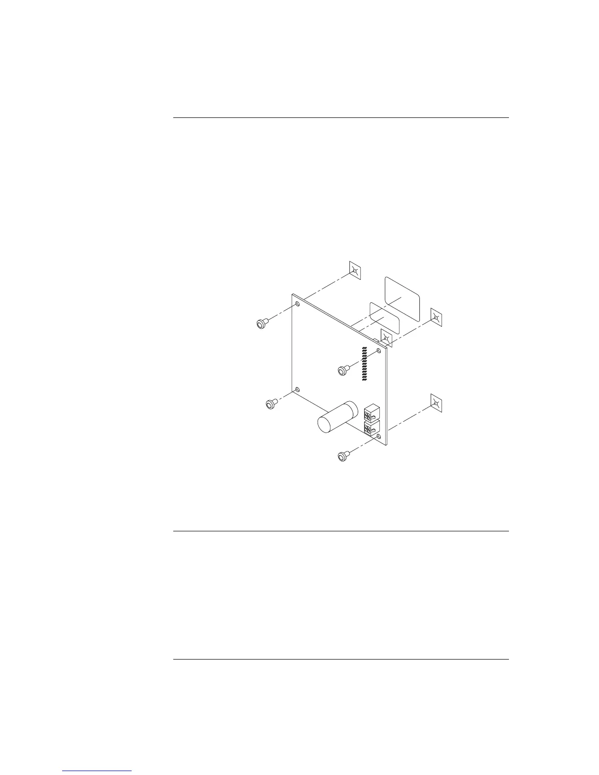
Refer to the figures and instructions below to mount the controller card assembly to the
back of one of the LED/switch cards.
4. Use four 322-123 Nuts and four 268-009 Washers to secure the 637-141 Bracket
to the inside front of the expansion box. Note that there are only two locations
where the bracket can be mounted, as shown in Figure 2-16.
5. Attach the header connector on the back side of the controller (P4) to the
connector on the back side of one of the LED/switch modules.
6. Secure the controller card to the board using four #6 screws, as shown in Figure
5.
Figure 2-17. Controller Card Mounting
WARNING: The 64/64 Controller Card cannot be mounted directly in front of a
4100 Motherboard or a Bay mounting bracket such as one that
mounts a T-Gen.
The 4100-1276 LED display card contains eight red LEDs and the 4100-1277 card
contains 16 alternating red/yellow LEDs. The LED colors may be configured differently,
as described in this section.
Only the following LEDs are to be used to change color configurations. LEDs are
available in sets of eight, as follows:
• 4100-9843 (yellow)
• 4100-9844 (green)
• 4100-9845 (red)
Continued on next page
Step 6. Installing LED/Switch Modules into Expansion Bays (4100U),
Continued
Mounting the
Controller Card
Assembly
Changing Display
Card LEDs