EasyManuals Logo

Simplex 4100U Installation & Maintenance

Simplex 4100U
180 pages
To Next Page IconTo Next Page
To Previous Page IconTo Previous Page
Page #124 background imageLoading...
Page #124 background image
8-2
The 4100U IDNet card receives 24V power (+24V Card Supply bus) and coms (i.e.
communication with the CPU) via the PDI. There are several versions, configured by
links soldered on the pcb. The 4100-3101 used in Australia, communicates with up to
250 devices. An IDNet card may be fitted to a 4100 (non-U) bay in an upgrade panel by
use of a bracket and interface pcb plus 4100 style power and coms wiring harness.
The part number for the IDNet card, plus Interface bracket is KT0452.
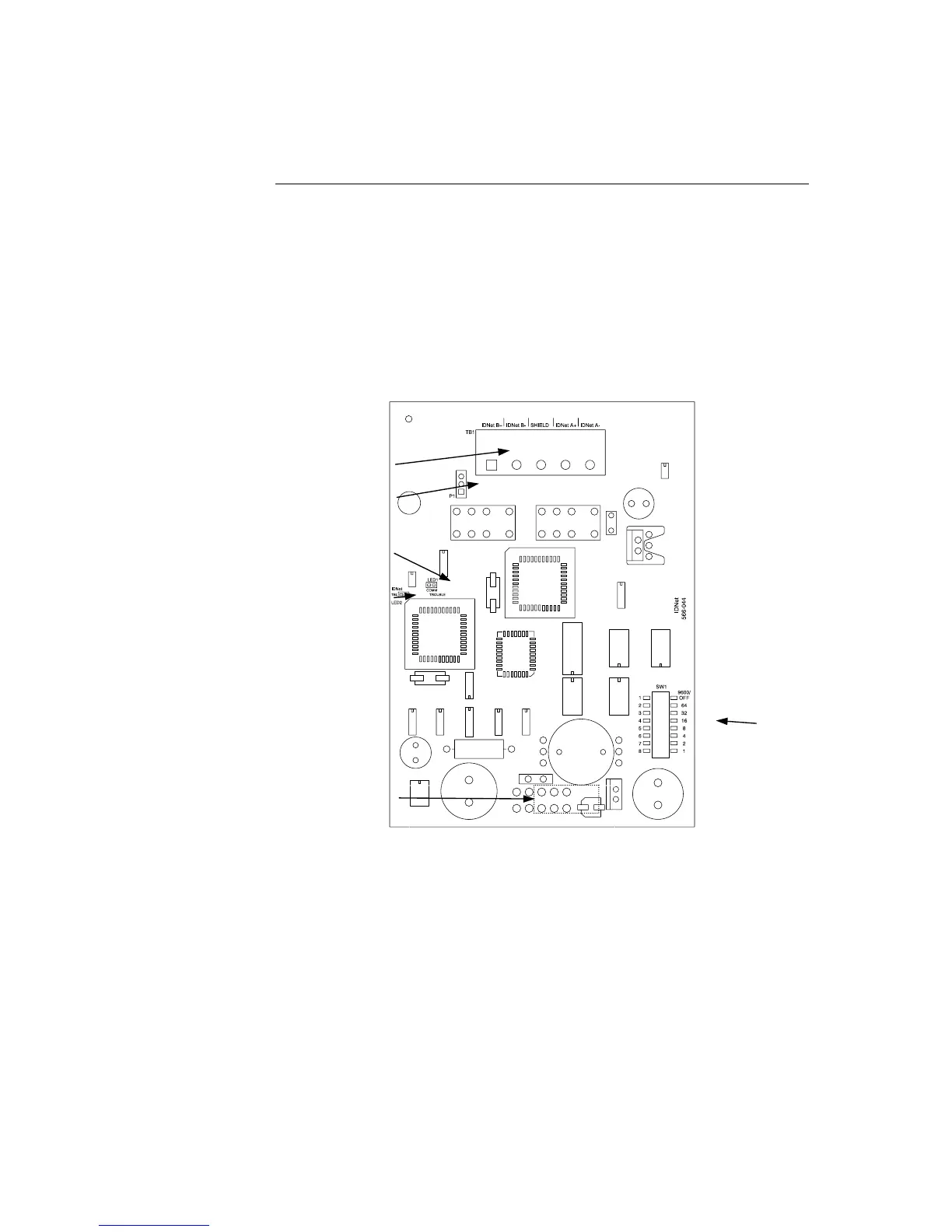
Figure 8-1. The IDNet Card
The IDNet Card
Overview
IDNET LINE TERMINAL BLOC
K
(TB1)
SHIELD JUMPER
(P1)
A
DDRESS
DIP SWITCH
(SW1)
COMM TROUBLE
LED (LED1)
IDNET TROUBLE
LED (LED2)
PDI CONNECTOR
(P2) (on reverse
side)

Table of Contents

Other manuals for Simplex 4100U

Questions and Answers:

Question and Answer IconNeed help?

Do you have a question about the Simplex 4100U and is the answer not in the manual?

Simplex 4100U Specifications

General IconGeneral
Control Panel TypeAddressable Fire Alarm Control Panel
DisplayLCD
Power Supply120/240 VAC, 50/60 Hz
Max Signaling Line Circuits (SLC)2
Operating Temperature0°C to 49°C (32°F to 120°F)
Humidity Range10% to 93% non-condensing
Network CapabilityYes
Communication ProtocolRS-232, RS-485
Battery Backup24 VDC
NAC Outputs4
Signaling Line Circuits (SLCs)2
Power Supply Current3.0 A
Max Notification Appliance Circuits (NAC)4
Max Releasing Circuits4
Max Relay Circuits4
Communication PortsRS-232, RS-485

Related product manuals