EasyManuals Logo

Simplex 4100U Installation & Maintenance

Simplex 4100U
180 pages
To Next Page IconTo Next Page
To Previous Page IconTo Previous Page
Page #95 background imageLoading...
Page #95 background image
5-15
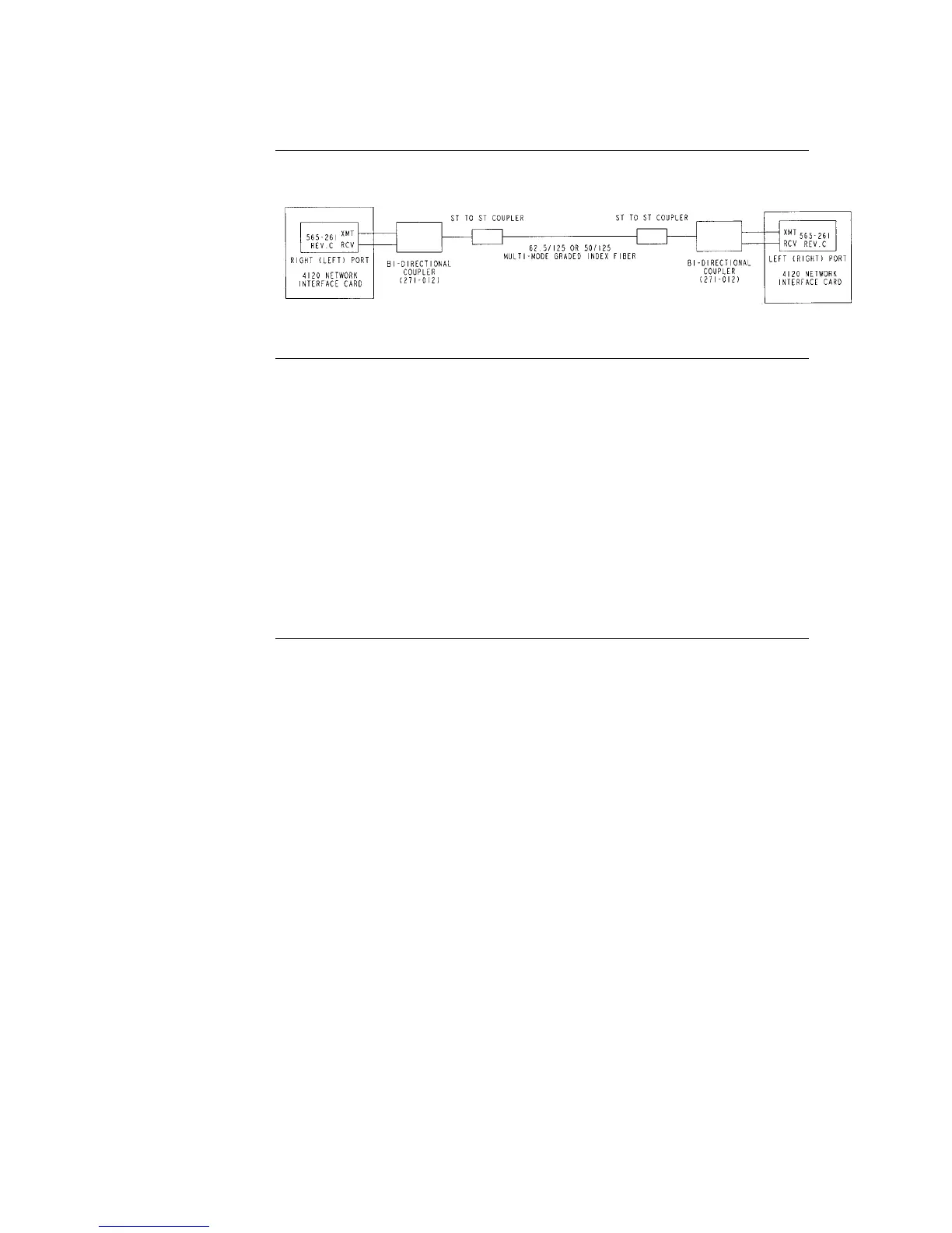
The illustration below shows coupler wiring.
Figure 5-10. Coupler Wiring
Refer to the guidelines and figures in this topic to use wired media cards.
IMPORTANT: TB1 on the wired media card must not be used when it is
connected to the 4100-6014 NIC.
When the 565-413 Interface Card is used with 565-516, -407, or –409 Network
Card, TB1 on the 565-413 Interface Card cannot be used. Connection to the
motherboard is required as shown.
The shield should only be connected at one end of the line. The shield is
connected to the left port.
When wiring leaves the building, 2081-9044 Overvoltage Protectors are
required. One overvoltage protector is installed where wiring leaves the building;
another is installed where wiring enters the next building.
Continued on next page
Step 4. Wiring Network Cards, Continued
4190-9010 Coupler
Requirements
(continued)
Wiring with the
Wired Media Card

Table of Contents

Other manuals for Simplex 4100U

Questions and Answers:

Question and Answer IconNeed help?

Do you have a question about the Simplex 4100U and is the answer not in the manual?

Simplex 4100U Specifications

General IconGeneral
Control Panel TypeAddressable Fire Alarm Control Panel
DisplayLCD
Power Supply120/240 VAC, 50/60 Hz
Max Signaling Line Circuits (SLC)2
Operating Temperature0°C to 49°C (32°F to 120°F)
Humidity Range10% to 93% non-condensing
Network CapabilityYes
Communication ProtocolRS-232, RS-485
Battery Backup24 VDC
NAC Outputs4
Signaling Line Circuits (SLCs)2
Power Supply Current3.0 A
Max Notification Appliance Circuits (NAC)4
Max Releasing Circuits4
Max Relay Circuits4
Communication PortsRS-232, RS-485

Related product manuals