3-35
This section contains guidelines and instructions for mounting the RUI and RIC II
modules into 4100 cabinets.
• The RUI motherboard mounts into the CPU bay or, if necessary, an expansion bay.
• The RIC II mounts into expansion bays only.
Review the following guidelines before installing a motherboard into a cabinet.
• If a power supply is installed in the bay, it must be installed on the far right of
the bay and any relay modules must be installed in the slots immediately to its
left.
• Relay cards must be installed in the rightmost possible slots. This is necessary
to allow for the proper routing of non-power limited wiring, which could be
connected to a relay module.
Mount the RUI motherboard (562-799 or 562-856) in a master controller bay as described
below.
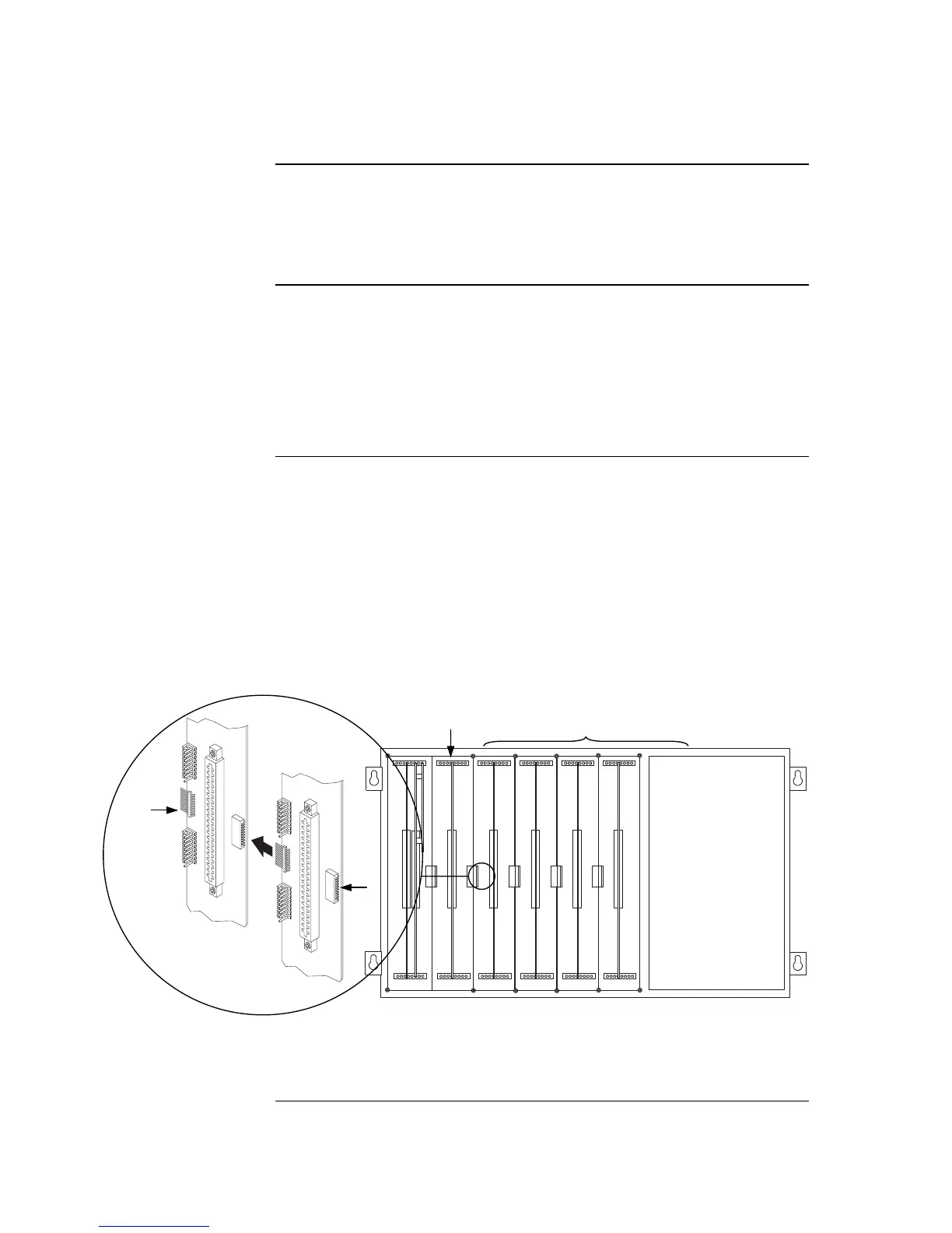
1. Orient the motherboard with the connector labeled J1 on the right and the header
labeled P1 on the left.
2. Match the connector on the previously installed motherboard with the pins on
the motherboard you are installing. Slide the motherboard to the left until the
pins are completely inserted in the connector of the previously installed
motherboard. If you are installing the leftmost board, the pins will remain
unconnected.
3. Secure the motherboard to the chassis with four torx screws.
Figure 3-4. Installing the RUI Motherboard in the CPU Bay
Note: RUI motherboards may also be installed in expansion bays. Refer to
“Step 5: Installing Motherboards into Expansion Bays (Non-4100U)” in
Chapter 2 for instructions.
Continued on next page
Installing Modules into Cabinets (Non-4100U)
Overview
Guidelines
Installing the
RUI Motherboard