EasyManuals Logo

Simplex 4100U Installation & Maintenance

Simplex 4100U
180 pages
To Next Page IconTo Next Page
To Previous Page IconTo Previous Page
Page #98 background imageLoading...
Page #98 background image
5-18
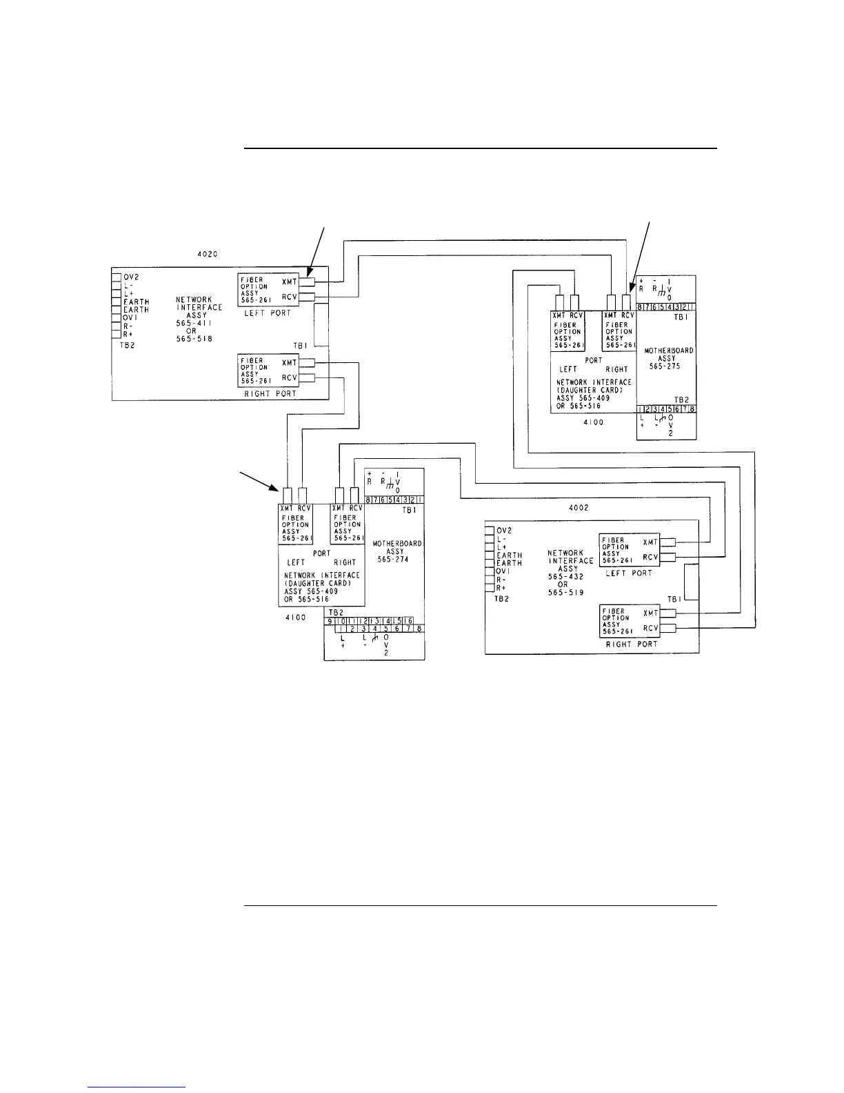
Figure 5-13. Fiber Optic, Style 7 Wiring
Continued on next page
Step 4. Wiring Network Cards, Continued
Fiber Optic,
Style 7 Wiring
Notes:
1. Refer to general wiring precautions in this chapter, as well as Field Wiring Specifications: document 900-082 for 4100;
900-242 for 4100U. For specific information about fiber optic wiring, refer to the 900-143 Fiber Tutorial.
2. The maximum distance between nodes when using the fiber communication path is dependent upon the fiber’s
multimode graded index: 10,000 feet (3,048 m) for 50/125 fiber; 15,000 feet (4,572 m) for 62.5/125 fiber. The maximum
cable O.D. is 0.118 (3 mm). Reference document 900-143 for other fiber sizes.
3. ST connectors with long strain relief boots are to be used with the fiber optic cable.
4. On assembly 565-274, JW1 and JW2 must be installed. Jumper plugs must not be installed on P5-P8.
5. Cable clamps supplied with 748-531 are used to secure the fiber cable.
SEE NOTE 5
SEE NOTE 5
SEE NOTE 5

Table of Contents

Other manuals for Simplex 4100U

Questions and Answers:

Question and Answer IconNeed help?

Do you have a question about the Simplex 4100U and is the answer not in the manual?

Simplex 4100U Specifications

General IconGeneral
Control Panel TypeAddressable Fire Alarm Control Panel
DisplayLCD
Power Supply120/240 VAC, 50/60 Hz
Max Signaling Line Circuits (SLC)2
Operating Temperature0°C to 49°C (32°F to 120°F)
Humidity Range10% to 93% non-condensing
Network CapabilityYes
Communication ProtocolRS-232, RS-485
Battery Backup24 VDC
NAC Outputs4
Signaling Line Circuits (SLCs)2
Power Supply Current3.0 A
Max Notification Appliance Circuits (NAC)4
Max Releasing Circuits4
Max Relay Circuits4
Communication PortsRS-232, RS-485

Related product manuals