EasyManuals Logo

Simplex 4100U Installation & Maintenance

Simplex 4100U
180 pages
To Next Page IconTo Next Page
To Previous Page IconTo Previous Page
Page #101 background imageLoading...
Page #101 background image
6-1
The SPS is described in Chapter 2. A picture is shown in Figure 2.4.
This chapter has the current and voltage ratings of the system power supply (SPS) and
describes how it is installed and configured by the factory. It also describes the Alarm
Relay Card that mounts onto the SPS to provide 3 extra relays.
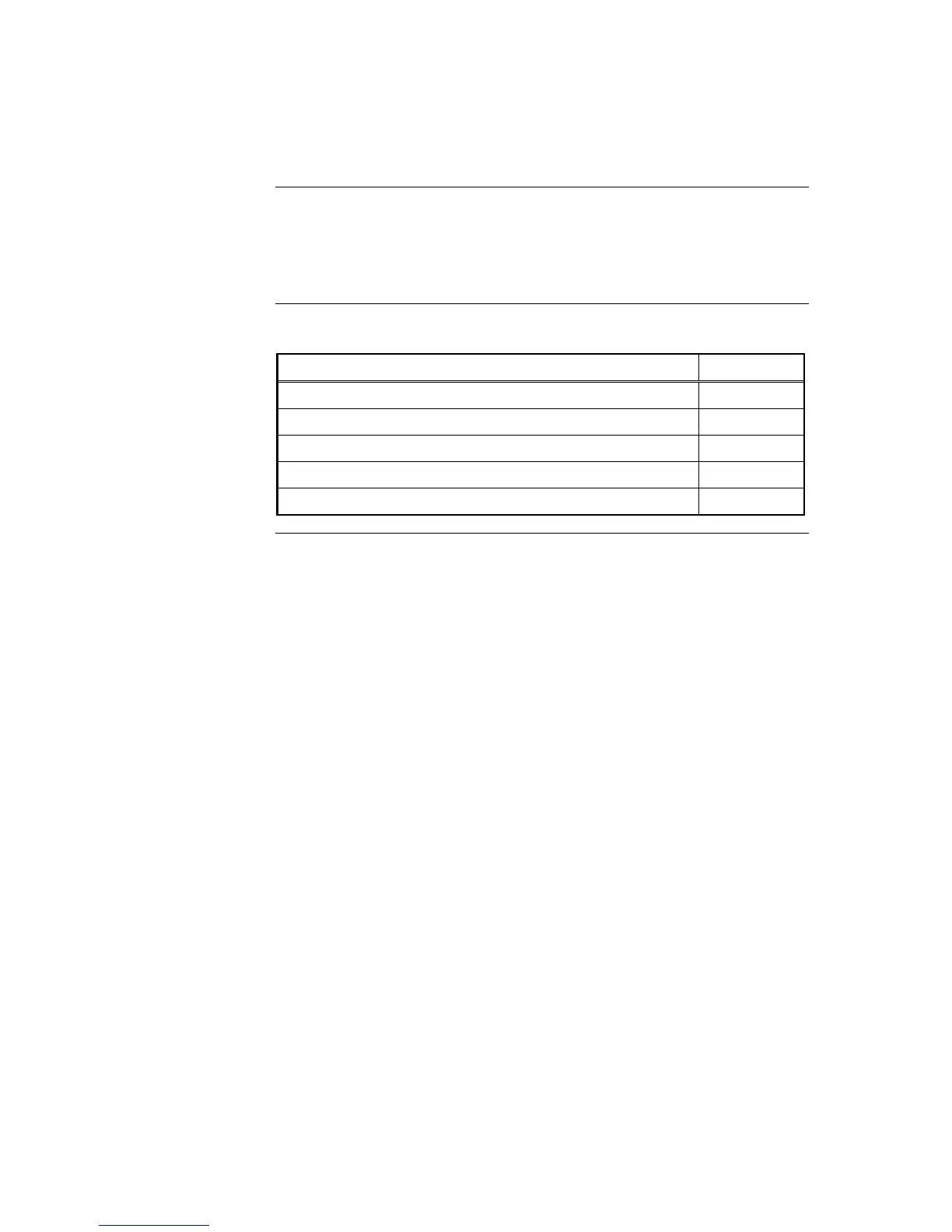
Refer to the page number listed in this table for information on a specific topic.
Topic See Page #
SPS Specifications
6-2
SPS Configuration
6-4
SPS LED Indications
6-5
Troubleshooting on SPS
6-6
The Alarm Relay Card
6-7
Chapter 6
The System Power Supply & Alarm Relay Card
Introduction
In this Chapter

Table of Contents

Other manuals for Simplex 4100U

Questions and Answers:

Question and Answer IconNeed help?

Do you have a question about the Simplex 4100U and is the answer not in the manual?

Simplex 4100U Specifications

General IconGeneral
Control Panel TypeAddressable Fire Alarm Control Panel
DisplayLCD
Power Supply120/240 VAC, 50/60 Hz
Max Signaling Line Circuits (SLC)2
Operating Temperature0°C to 49°C (32°F to 120°F)
Humidity Range10% to 93% non-condensing
Network CapabilityYes
Communication ProtocolRS-232, RS-485
Battery Backup24 VDC
NAC Outputs4
Signaling Line Circuits (SLCs)2
Power Supply Current3.0 A
Max Notification Appliance Circuits (NAC)4
Max Releasing Circuits4
Max Relay Circuits4
Communication PortsRS-232, RS-485

Related product manuals