1-6
The 4100 can be expanded to a network system by using network interface cards (NICs).
When a NIC is installed into a 4100 host panel, it is used to connect to other network
nodes. Nodes may consist of other host 4100 panels, or they may be completely different:
Graphical Command Centers (GCCs), and Visual Command Centers (VCCs) are all
examples of what could be used as nodes. A node is a self-sufficient CPU that controls
appliances and devices, which also has the capability of controlling and communicating
with other nodes.
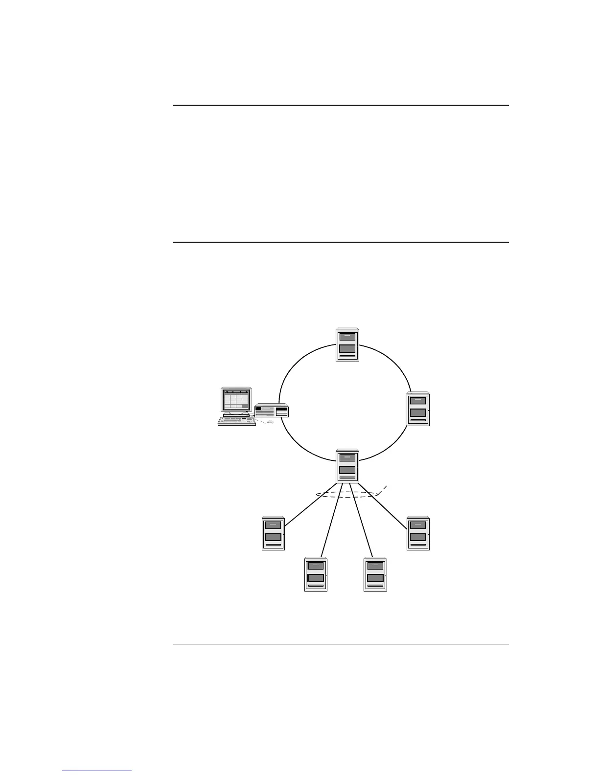
The network configuration supports two prevalent architectures (or wiring
configurations): hub (or ring), or star. A networked system can also use a combination of
the two.
The hub configuration consists of a main loop with nodes connected in a radial manner.
The star configuration consists of several nodes connected directly to one common node.
Physical bridge cards are used for the star configuration. Physical bridges reduce the
amount of wire that would otherwise be needed to connect all nodes in a loop, and
therefore cut down on system response time. A combination of the two styles is illustrated
in Figure 1-3.
Ring Topology
Physical Bridge Links
(Star Topology)
Graphic Command
Center (GCC)
Network Display Unit
(NDU) Hub Node
Distributed Remote
Node Locations
Figure 1-3. Hub/Ring Configuration
Continued on next page
Network Configuration
Overview
Hub and Star
Configurations