LC700 – User’s Guide
3.62
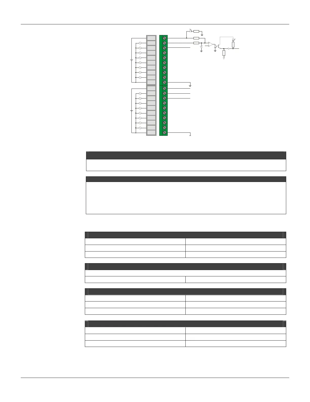
Green
IMB
R
Yellow
Vcc
In1A
In2A
In1B
ext1
ext2
In2B
1A
2A
3A
4A
5A
6A
7A
8A
9A
10A
1B
2B
3B
4B
5B
6B
7B
8B
9B
10B
PWR-A
PWR-B
GND-A
GND-B
Figure 3. 37- External Connection
NOTE
To comply with the EMC standards, use shielded cables in signal inputs (ground the shield in the panel only
in one side of the cable) and cables less then 30 meters for power source inputs.
IMPORTANT
This module has 12-bit counters to accumulate up to 4096 pulses, for each one of 16 channels, before a
overflow occurs. Therefore, considering the maximum operation frequency, it has the following minimum
overflow time:
• M-304: 4096 pulses / 10000 Hz = 0,4096 s
The system macro-cycle must be lower than the pulse counter module overflow time.
Technical Specifications
ARCHITECTURE
Number of inputs 16
Number of groups 2
Number of points per group 8
ISOLATION
Groups are isolated separately
Optical isolation up to 5000 Vac
EXTERNAL SOURCE
Source 20-30 Vdc
Typical consumption per group 12 mA @ 24 Vdc
Power Supply Indicator Green LED
INTERNAL SOURCE
Provided by the IMB bus(5 VDC) 130 mA
Maximum total dissipation 650 mW
Power Supply indicator None