LC700 – User’s Guide
3.4
Module Specification Format
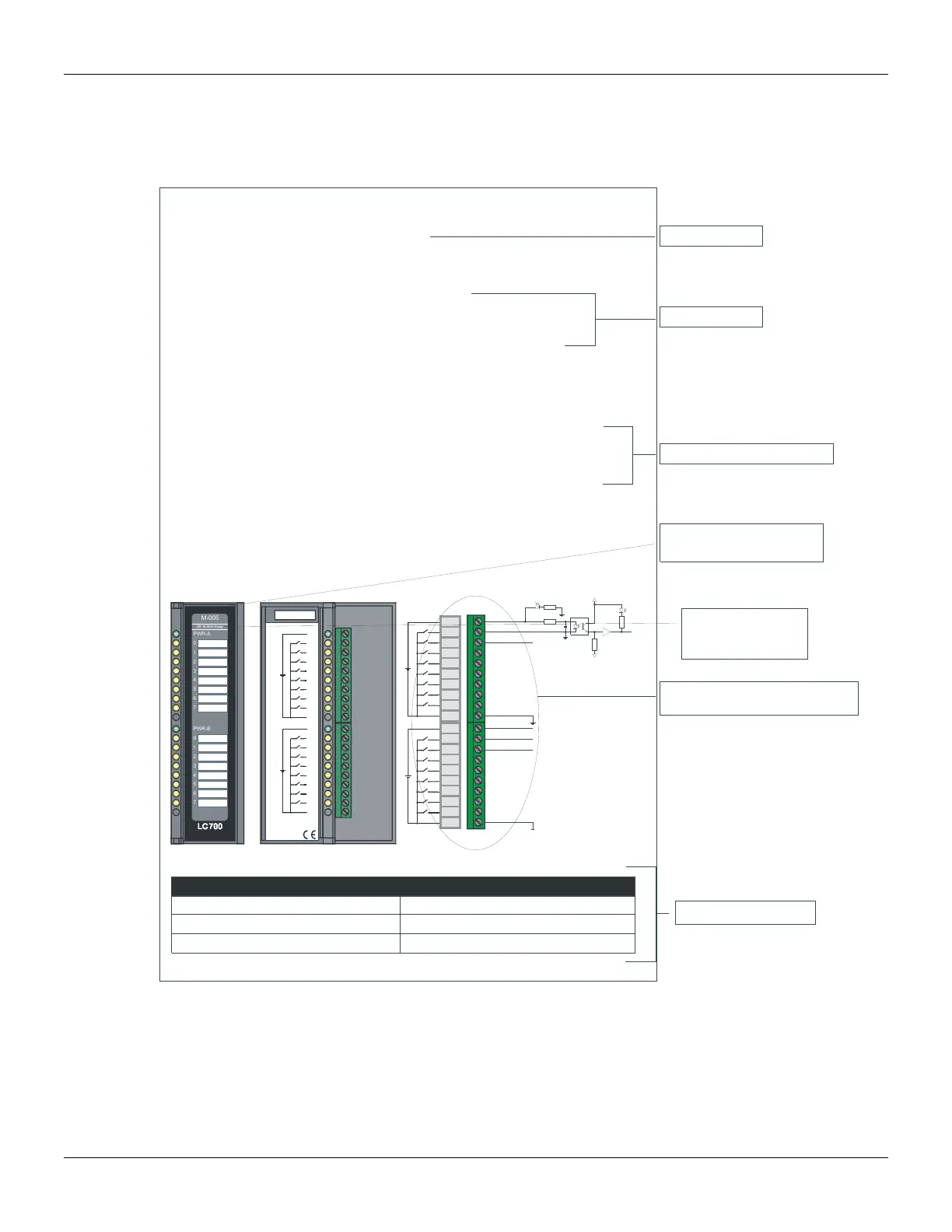
The module specification is shown in a format similar to the example below. The Module
specifications explain functionality, field connection, and electrical characteristics. It also shows a
simplified schematic of the interface circuit for better understanding.
R
cc
Yellow
Green
IMB
In1A
In2A
In1B
ext1
ext2
In2B
1A
2A
3A
4A
5A
6A
7A
8A
9A
10A
1B
2B
3B
4B
5B
6B
7B
8B
9B
10B
PWR-A
PWR-B
GND-A
GND-B
005/15 - 2 Groups 8 24VDC Digital Inputs - Sink
1A
2A
3A
4A
5A
6A
7A
8A
9A
10A
1B
2B
3B
4B
5B
6B
7B
8B
9B
10B
PWR-A
PWR-B
GND-A
GND-B
1
2
3
4
5
6
7
PWR-B
0
1
2
3
4
5
6
7
smar
0
M-005
PWR-A
ID & Hot-Swap
smar
Architecture
Inputs
Groups
Points per Group
16
2
8
Technical Specification
External Connections Diagram and
Simplified Internal Circuit Diagram
DC INPUT MODULE M-005
(SUPPORTS HOTSWAP E DEVICE ID)
Part Number
M-005 (2 groups of 8 inputs 24 Vdc isolated)
Module Name
Part Number
Description
The module senses the DC input voltage and coverts it into a
True (ON) or False (OFF) logic signal. It has 2 optically isolated
Groups of 8 inputs.
Brief Description of the Module
Frontal Panel with labels
Of the Channel Tags
Indicates if the module
supports Hot Swap
and Device ID
Figure 3.1 – Module Specification Format