LC700 Architecture
2.3
C – DF90 cable – Cable for IMB power transmission. In this cable is the Vcc and GND of IMB and it
has to be connected in the rack’s left side.
D – Module support - Module holder located in the top of the rack.
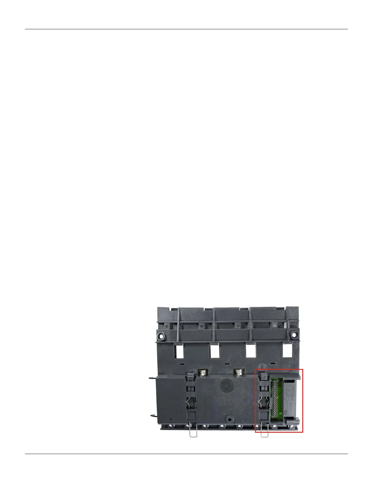
E – Flat Cable Connector (rear) – It allows that two racks are interconnected by flat cable (P).
When there is more than one rack in a same DIN rail, the user should proceed as described in the
“Connection between adjacent racks” topic.
F – W1 Jumper – To disconnect the rack from the power of the previous rack, W1 must be cut,
together with the Vcc connection plate (L) of the previous rack. This condition is necessary if a new
power supply is inserted from this rack.
G – Module connector – Connector to attach the module’s bottom part to the rack.
H – Clips – The metal clips, located in the rack’s bottom part, allow attaching the rack to the DIN
rail. They must be pulled before fitting the rack on DIN rail, and then, pushed for pieces fixation.
I – Grounding plate (housing)
J – Address switch – When there is more than one rack in same data bus, the addressing switch
allows different addresses to each rack.
K – LED for diagnostic – It is used for diagnostic of the rack’s voltage.
L – Vcc connection plate – Vcc terminal (for power transmission).
M – GND connection plate - GND terminal (for power transmission).
N – Flat Cable Connector (top) – It allows that two racks are interconnected by flat cable (P).
When there is more than one rack in a same DIN rail, the user should proceed as described in the
“Connection between adjacent racks” topic.
O – Ground terminal – It is used to ground the flat cables shield.
P – Flat Cable – Cable used to interconnect the data bus among racks.
Q – Connector cap – To meet the EMC requeriments a protector against ESD must be installed in
the flat cables connections, at right.
Installing Racks - DF93
Figure 2.3 - Rear connector of DF93 rack