Chapter 2
2.1
LC700 ARCHITECTURE
Racks and Modules
The most important elements of an LC700 system are the Racks and Modules. To build a LC700
system, we basically need a CPU Module, one or more Power Supply Modules and a set of I/O
Modules to interact with field signals.
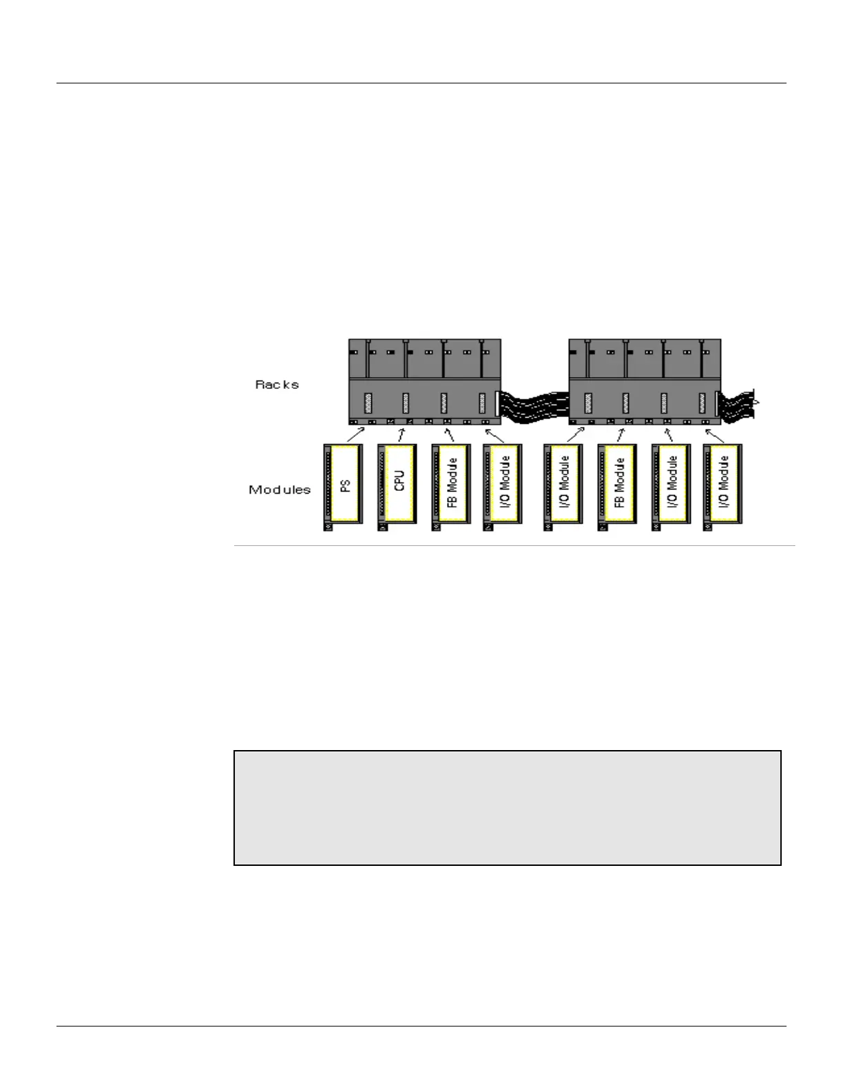
Modules are plugged into the Slots that are part of the Racks. The Slots connect the Modules
through a common bus called Inter-Module-Bus (IMB) used by the CPU to communicate with them.
Racks can be interconnected for system expansion. Each Rack has four (4) Slots. This means that
every added Rack makes room for four (4) extra Modules (See Figure 2.1).
Figure 2.1 - Racks and Modules
One LC700 system can have up to fifteen (15) Racks. This implies a maximum of sixty (60) Modules
per system.
This section provides instructions on how to build an LC700 system. The next topic will describe the
basic components of an LC700 system and how to install them.
Basic Components
Rack - A Rack is basically a plastic support for the Inter-Module-Bus (IMB) that carries connectors
for the plugs for the Modules. These connectors that fit the Modules are called Slots.
Notes:
The Rack has a rotating switch where one address can be selected. Possible
addresses are: 0, 1, 2, 3, 4, 5, 6, 7, 8, 9, A, B, C, D, E.
Note that the “F” is not a possible address.
The main function of IMB is transporting the signals between the Modules and the
CPU.
Module - Plastic box with a labeled cover explaining the terminal connections. There are many
types of Modules offered for the applications (see Modules and Accessories section). The main
Module is the CPU-Module. It is responsible for executing the user configuration during run time.
There are other Modules such as: Power Supply, Discrete I/O, Analog I/O, High Speed Counters,
Motor Controllers, fieldbus scanners, Remote I/O, etc.