Modules And Accessories
3.35
Technical Specifications
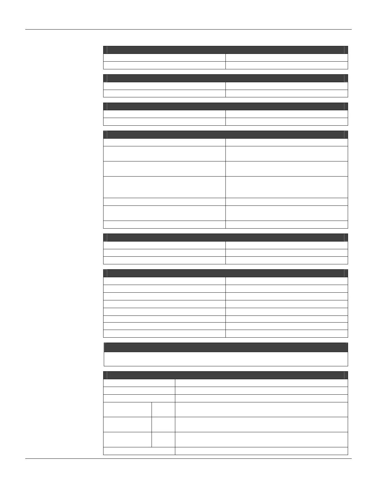
CONFIGURATION MEMORY
Type
Non volatile Memory (NVRAM)
Available Size 44 Kbytes
NUMBER OF AVAILABLE POINTS FOR CONFIGURATION
Digital Points
2000 (discrete and auxiliary points)
Analog Points 1024
CONFIGURATION/OPTIMIZATION
Software Package CONF700 Version 8.54
Operational System Windows 2000 and Windows XP
COMMUNICATION PORTS
Quantity 3
Types
1-EIA-232-C (P1)
2-EIA-485 (multidrop, P2 e P3)
Connectors
Female DB9 to EIA-232-C (P1)
Terminal blocks for EIA-485, remote I/O
Baud Rate/Address
P1: 9600 bps
P2: 9600– 115200 bps
P3: 57600-230400 bps
Protocol Modbus RTU (Slave)
Slave Address
2 a 127, Set by User(1 is default)
2 to 121, set by user (1 is the default address)
Maximum number of LC700 per network 31
INTERNAL POWER
Provided by the IMB bus 5 Vdc, @ 320 mA
Total Maximum Dissipation
1.6 W
Power Indicator
Green LED, +5VDC
FAILURE RELAY
Output type Solid state relay, Normally Close (NC)
Limits 6 W, 30 Vdc Máx, 200 mA Máx.
Maximum Initial Contact Resistance <13Ω
Status Indication Red LED- FAIL
Logic Indicator LED ON (relay closed)
Over Load Protection: Should be provided externally
Operation Time 5 ms maximum
Release Time 5 ms maximum
NOTE
To meet the EMC standards requirements, the wires’ length to the failure relay must be less than 30 meters.
The power supply of activated load by the failure relay must not be from external network.
OTHER LEDS
RUN Green LED- indicates program running
HOLD Yellow LED- indicates program in hold mode
FORCE Red LED- indicates all inputs and/or outputs are in the force mode.
Rx (Yellow LED)
Tx (Green LED)
P1 Displays Modbus Communication (EIA-232)
Rx (Yellow LED)
Tx (Green LED)
P2 Displays Modbus Communication (EIA-485)
Rx (Yellow LED)
Tx (Green LED)
P3 Displays Modbus Communication (EIA-485)
FAIL Red LED- Indication of failure