LC700 – User’s Guide
3.50
The positive pole can be also connected to the 1A and 1B terminals. It makes the Green LED turns
on indicating the powering is ON, but it does not have other function.
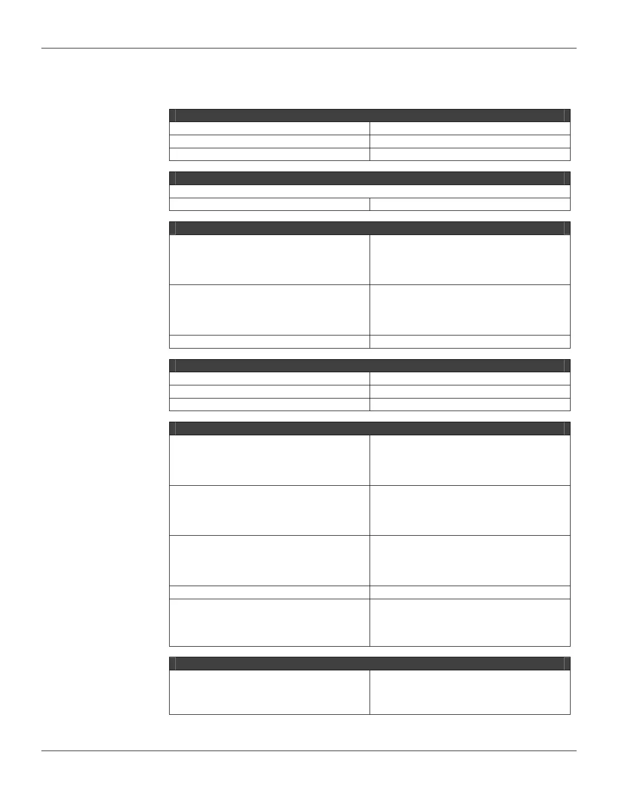
Technical Specifications
ARCHITECTURE
Number of Inputs 16
Number of groups 2
Number of points per group 8
ISOLATION
Groups are isolated individually
Optical Isolation up to 5000 Vac
EXTERNAL POWER
Voltage Source for inputs
20 - 30 Vdc (M-001)
36 - 60 Vdc (M-002)
45 - 75 Vdc (M-003)
95 - 140 Vdc (M-004)
Maximum Consumption per Group
65 mA @ 24 Vdc (M-001)
65 mA @ 48 Vdc (M-002)
62 mA @ 60 Vdc (M-003)
40 mA @ 125 Vdc (M-004)
Power Supply Indicator Green LED
INTERNAL SOURCE
Provided by the IMB bus 5 Vdc @ 80 mA maximum
Total Maximum dissipation 0.4 W
Power Supply Indicator None
INPUTS
ON State Voltage Range (logic “1”)
20-30 Vdc (M-001)
30-60 Vdc (M-002)
38-75 Vdc (M-003)
95-140 Vdc (M-004)
OFF State Voltage Range (logic “0”)
0-5 Vdc (M-001)
0-9 Vdc (M-002)
0-12 Vdc (M-003)
0-25 Vdc (M-004)
Input Impedance (typical)
3.9 kΩ (M-001)
7.5 kΩ (M-002)
10 kΩ (M-003)
39 kΩ (M-004)
Status Display Yellow LED
Input Current per Point
8 mA @ 24 Vdc (M-001)
8 mA @ 48 Vdc (M-002)
7.5 mA @ 60 Vdc (M-003)
5 mA @ 125 Vdc (M-004)
SWITCHING INFORMATION
Minimum Voltage for logic level “1”
20 Vdc (M-001)
30 Vdc (M-002)
38 Vdc (M-003)
95 Vdc (M-004)