LC700 – User’s Guide
3.46
PS302P/PS302P DC - FIELDBUS POWER SUPPLY MODULE
Part Number:
PS302P (AC Power Supply)
PS302P DC (DC Power Supply)
These modules were specially developed to power the fieldbus networks. The only difference
between the modules is the input voltage:
PS302P (90 ~264 Vac)
PS302P DC (20 ~30 Vdc)
The PS302P power supply unit is a non-intrinsically safe equipment with a universal AC input (90 to
264 Vac, 47 to 63 Hz or 127 to 135 Vdc), and a 24 Vdc isolated output, with short-circuit and
overcurrent protection, ripple and fault indication, appropriated to power fieldbus elements.
The PS302P DC power supply unit is a non-intrinsically safe equipment with a DC input (20 to 30
Vdc) and a 24 Vdc isolated output, with short-circuit and overcurrent protection, ripple and fault
indication, appropriated to power fieldbus elements.
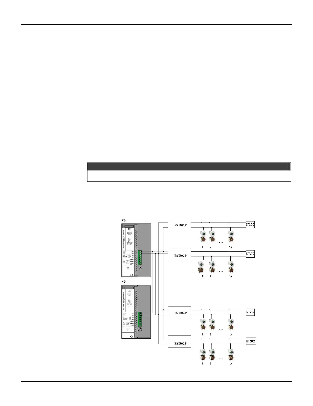
The interconnection of Fieldbus elements to the PS302P/PS302P DC unit shall be done as shown in
figure below. There is no overshoot when it is switched on or off. The PS302P/PS302P DC can
power on up to 4 fully loaded Fieldbus elements.
OBSERVATION
Cables that interconnect the PS302P/PS302P DC to PSI302P modules should have a maximum
of 3 meters
If any abnormal condition occurs in the output like overloading or short-circuiting, the
PS302P/PS302P DC internal switching is automatically switched off, thus protecting its circuit. Upon
the outputs return to normal conditions of operation, the circuit is automatically switched on.
The PS302P/PS302P DC allows redundancy without requiring any component coupled to its output.
Figure 3.21 - Connection Diagram of Fieldbus Elements to PS302P