Modules And Accessories
3.89
Technical Specifications
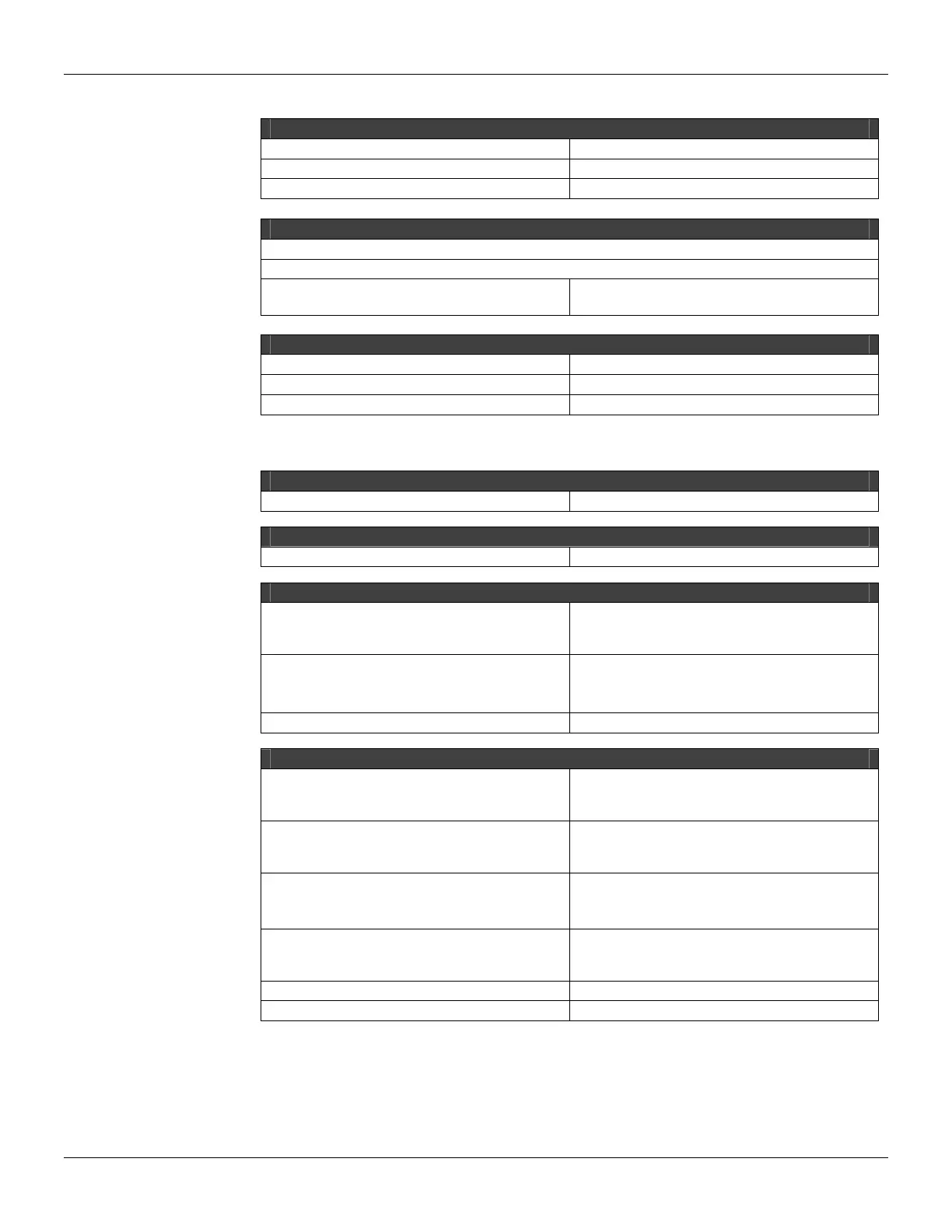
ARCHITECTURE
Number of groups 2
Number of Vdc inputs 8
Number of outputs 4
ISOLATION
Groups are individually isolated
8 individually isolated relay contacts. The power supply for the groups is individually isolated.
The driver for each relay is optically Isolated
from IMB up to:
5000 Vac
INTERNAL POWER
Provided by the IMB bus: 5 Vdc @ 60 mA typical
Total Maximum Dissipation 0.3 W
Indicator Of Source None
For the Vdc Inputs:
ARCHITECTURE
Number of Points 8
ISOLATION
Isolation up to 5000 Vac
EXTERNAL POWER
Voltage Source for Inputs
20-30 Vdc (M-201, M-204, M-207)
36-60 Vdc (M-202, M-205, M-208)
45-75 Vdc (M-203, M-206, M-209)
Maximum Consumption per Group
65 mA @ 24 Vdc (M-201)
65 mA @ 48 Vdc (M-204)
62 mA @ 60 Vdc (M-207)
Power Supply Indicator Green LED
INPUTS
ON State Voltage range (logic “1”)
20-30 Vdc (M-201, M-204, M-207)
30-60 Vdc (M-202, M-205, M-208)
38-75 Vdc (M-203, M-206, M-209)
ON State Voltage range (logic “0”)
0-5 Vdc (M-201, M-204, M-207)
0-9 Vdc (M-202, M-205, M-208)
0-12 Vdc (M-203, M-206, M-209)
Input Impedance (Typical)
3,9 K
Ω (M-201, M-204, M-207)
7,5 K
Ω (M-202, M-205, M-208)
10 K
Ω (M-203, M-206, M-209)
Input Current per Point
8 mA @ 24 Vdc (M-201, M-204, M-207)
8 mA @ 48 Vdc (M-202, M-205, M-208)
7,5 mA @ 60 Vdc (M-203, M-206, M-209)
Status display Yellow LED
Indicator Logic On when active