LC700 – User’s Guide
3.90
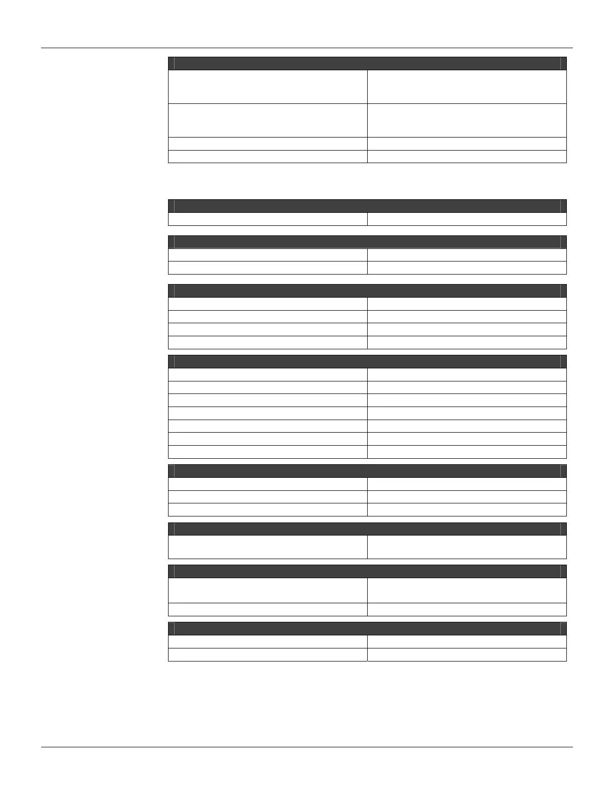
SWITCHING INFORMATION
Minimum Voltage for logic level “1”
20 Vdc (M-201, M-204, M-207)
30 Vdc (M-202, M-205, M-208)
38 Vdc (M-203, M-206, M-209)
Maximum Voltage for logic level “0”
5 Vdc (M-201, M-204, M-207)
9 Vdc (M-202, M-205, M-208)
12 Vdc (M-203, M-206, M-209)
Time from “0” to “1” 30 μs
Time from “1” to “0” 50 μs
For the Relay Outputs:
ARCHITECTURE
Number Of Outputs 4
ISOLATION
Group is individually isolated Each Relay has two dedicated Terminals
Optical Isolation up to: 5000 Vac (Before the Relay Isolation it self)
EXTERNAL SOURCE
Voltage Source for each Group 20-30 Vdc
Maximum Consumption per Group 52 mA @ 24 Vdc
Typical Consumption per Point 12 mA @ 24 Vdc
Power Supply Indicator per Group Green LED
OUTPUTS
Vac Range 20-250 Vac
Vdc Range 20-110 Vdc
Maximum Current for 250 Vac 5A (Resistive);
Maximum Current for 30 Vdc 5A (Resistive)
Status display Yellow LED
Indicator Logic ON if the relay coil is active
Leakage 500 μA @ 100 Vac
SWITCHING INFORMATION
RC Protection Circuit 62 Ω in series with 0.01 uF
Time to activate 10 ms
Time to deactivate 10 ms
ELECTRICAL SERVICE LIFE
Switching Cycles
100.000 operations minimum @ maximum
current
DIMENSIONS AND WEIGHT
Dimensions (W x D x H)
39.9 x 137.0 x 141.5 mm;
(1.57 x 5.39 x 5.57 in)
Weight 0.298 kg
CABLES
One Wire 14 AWG (2 mm
2
)
Two Wires 20 AWG (0.5 mm
2
)