Modules And Accessories
3.107
ICS2.0P - Serial Converter Interface Module
Part Number
ICS2.0P (Serial Converter Interface)
Description
The serial converter interface ICS2.0P is a device composed of an universal power supply and
inputs and outputs for both standards 232 and 485 interfaces. The three modules (power supply,
232 interface and 485 interface) are electrically isolated resisting typically to voltages up to 1600
V
RMS
(1 minute) or 2000 V
RMS
(1 second).
Due to its particular feature, where two communication interfaces with different communication
modes are connected (232 is full Duplex while 485 is Half Duplex), this interface allows to choose
between Full Duplex and Half Duplex in the 232 interface. Besides, because the 232 interface is
used in point-to-point communications and the 485 interface is mostly used in multidrop
communications, an automatic mechanism toggles the 485 transmission despite the selected baud
rate.
The Bus Busy feature checks if the 485 line has a present signal or if it is on break mode. In this
case, this circuit blocks any signal from the 232 bus to the 485 bus.
For more details about this interface, consult its manual.
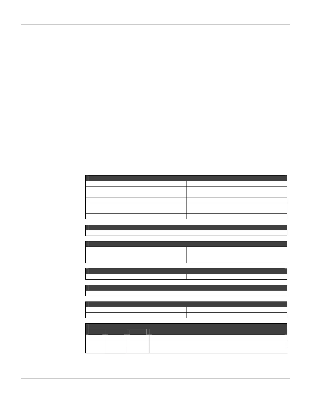
Technical Specifications
POWER SUPPLY
Consumption 3 W max.
Input Voltage
90 to 240 Vac @ 48 to 70 Hz, simple or two-
phase.
Output Voltage 5 Vdc, 0.5 A max.
Protection
Against overcurrent, overvoltage and
instantaneous surge and EMI.
Protection Fuse 250 mA
CERTIFICATION
According to CE.
ISOLATION
Optical and Galavanic
Up to 1600 V
RMS
(1 minute)
2000 V
RMS
(1 second) between the network
source and the buses among the buses..
BAUD RATE
Baud Rate Up to 250 Kbps, auto adjustable.
INDICATION
Energization LEDs and presence of communication of signal.
TEMPERATURE
Operation -10 to 60 ºC @ 100% RH max.
Storage -30 to 90 ºC @ 90% RH max.
CONNECTION
Pin I/O Signal Description
1 I L Phase input
2 I N Neutral input (single phase)/ Phase (two-phase)
3 - G Housing grounding pin
Connection: 3 wires, L, N, G, through terminals with screw.
OBS: When using the two-phase input, we recommend the use of an external fuse in the N line.