Modules And Accessories
3.45
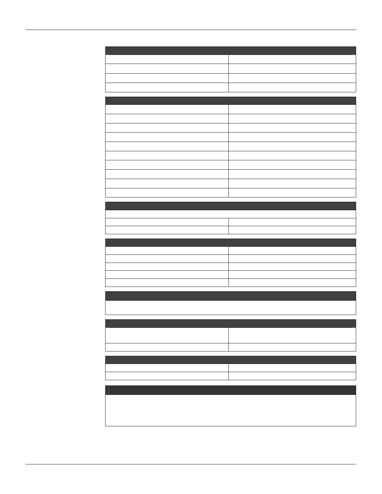
Technical Specifications
INPUTS
DC 20 to 30 Vdc
Inrush Current
< 20.6 A @ 30 Vdc [ ΔT < 430 us]
Maximum consumption 42 W
Indicator DC LINE (Green LED)
OUTPUTS
a) Output1 (internal use) 5.2 Vdc +/- 2%
Current 3 A Maximum
Ripple 100 mVpp Maximum
Indicator +5 VDC (Green LED)
Hold up Time > 47 ms @ 24 Vdc [Full Load]
b) Output 2 (external use) 24 Vdc +/- 10%
Current 300 mA Maximum
Ripple 200 mVpp Maximum
Short circuit Current 700 mA
Indicator +24 VDC (Green LED)
ISOLATION
Output (external and internal) and Input are isolated.
Between outputs and ground 500 V
RMS
Between input and output 1500 V
RMS
FAILURE RELAY
Output Type Solid State relay, Normally Closed (NC)
Limits 6 W, 30 Vdc max, 200 mA max.
Maximum Initial Contact Resistance <13Ω
Overload Protection Should be set externally
Operation Time 5 ms maximum
NOTE
To meet the EMC standards requirements, the wires’ length to the failure relay must be less than 30 meters.
The power supply of activated load by the failure relay must not be from external network.
DIMENSIONS AND WEIGHT
Dimensions (W x D x H)
39.9 x 137.0 x 141.5 mm;
(1.57 x 5.39 x 5.57 in)
Weight 0.450 kg
CABLES
One Wire 14 AWG (2 mm
2
)
Two Wires 20 AWG (0.5 mm
2
)
NOTES
1. If the power consumption exceeds the power supplied, the LC700 system may operate in an unpredictable
manner that may causes damages to the equipment or risk of personal injury. Therefore, the power
consumption must be calculated correctly and a detailed analysis should be performed to define the
installation of extra power supply modules.
2. The previous revisions of GLL1279 Rev2 do not support redundancy feature.
Calculating Power Consumption
Refer to the topic at the end of the technical specification table of the AC Power Supply for further
information.