LC700- Manual de instalação
4.13
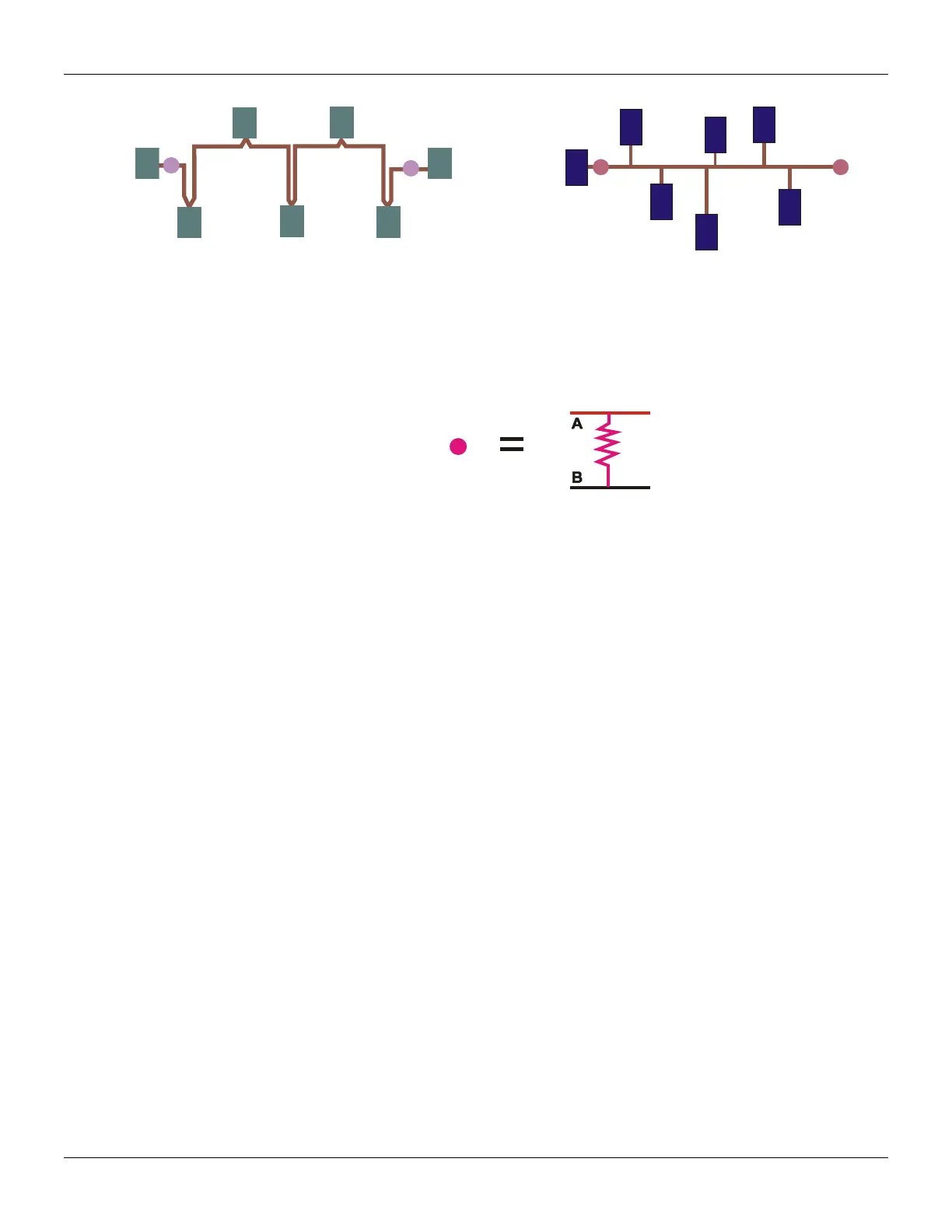
Figure 4.14 – Terminators for EIA-485 Network
Figure 4.15 - Terminator
3. Terminators
The terminators value should be according to the characteristic impedance of the transmission
line cable and it should be installed in parallel to the A and B lines, accordingly Figures 4.14 and
4.15.
1/4W
Terminator
Resistor
Figure 4.16 – Resistor Value Equal to Zo (Line Characteristic Impedance)
4. Use cables projected for RS-485.
Summary of Panel Mounting Basic Rules
1. Install electronic equipments Controllers (CLP), Transmitters, Computers in a noise-free
power line. Never connect electronic equipments in a noisy power line;
2. Avoid Inductive Loads (solenoid valves, motors) close to electronic equipment inside the
electronic panel, if necessary separate them as far as possible.
3. Connect a suppressor in parallel to the inductive load;
4. Separate the wires according to their Categories;
5. Use a line filter in the panel power inputs: This will prevent receiving or sending noises
through the electric installation;
6. Make a good grounding for the racks;
7. Connect the power supply ground, the filter for common mode and for electrostatics
discharges, will be more effective;
8. Separate the power distribution in the panel;
9. Use shielded cable for signals coming from the field;
10. The shield should be grounded in a single point;
11. Adopt Ferrite to filter high frequency noises from lines that come from the field. Apply in
lines that are exposed to noisy ambients;
12. Avoid circuit loops;