LC700 – User’s Guide
3.38
Warning
The address and baud rate of the RIO-700-E3 interface module must be set. Interface modules
and power supply modules for remote I/O are automatically set.
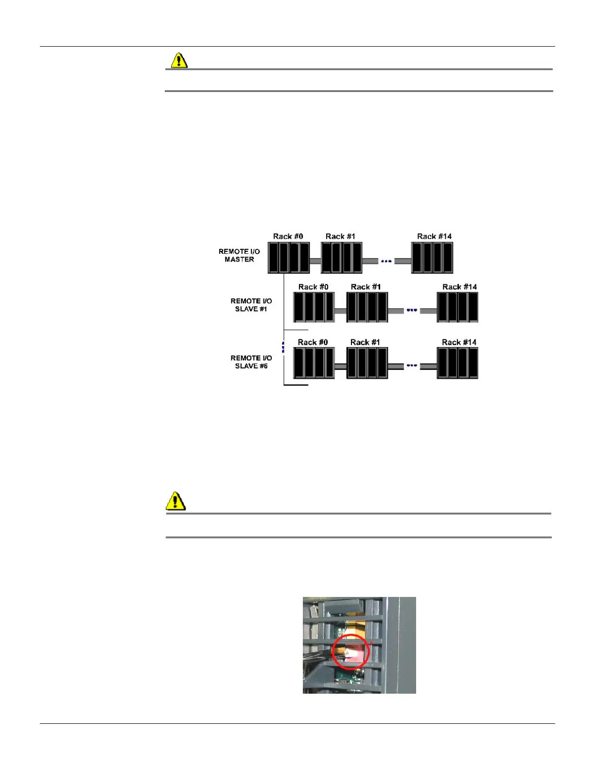
Remote I/O Architecture
The Remote I/O System is basically composed of a Master Unit and up to 6 Slave Units. Master Unit
and Slave Units are connected through a multi-drop cable that can reach a total length of 4000ft.
The proper cable length and baud rate depend on the level of noise in the application environment.
The available Rack/Slots will limit the total number of modules per System and the maximum
number of Discrete and Analog Points that the LC700 will be able to handle.
Each Remote I/O needs, at least, one power supply. LC700 Remote I/O system structure is shown
as follows:
Figure 3.17- Remote I/O Architecture
Baud Rate and Address Settings
Baud Rate Settings
Each Remote I/O Interface Module (Master or Slave) has a DIP switch to set the baud rate
(communication speed). The DIP switch is located in the frontal panel of the Module and can be
accessed with a small screw driver.
Observation:
Make sure to disconnect the Module while setting the switch. Also note that both the Master and
Slave I/O interface must be configured with the same baud rate.
Setting Address of the Remote I/O Interface Module
There is also a dedicated Rotary Switch at the bottom of the Slave Module to set the Slave device
address. Each Remote Unit connected to the Master Unit has to have a unique address. Available
addresses are: 1, 2, 3, 4, 5 and 6.