LC700 – User’s Guide
3.124
Cables for Racks Interconnection and Power Distribution
Depending on the rack model different types of cables are necessary to interconnect racks and for
power distribution throughout the IMB bus. In the following table are the available cable types.
System based on DF93
Code Description
DF90 IMB power cable
DF101 Shielded flat cable to connect racks by left side – length 70 cm
DF102 Shielded flat cable to connect racks by right side – length 65 cm
DF103 Shielded flat cable to connect racks by right side – length 81 cm
DF104 Shielded flat cable to connect racks by right side – length 98 cm
DF105 Shielded flat cable to connect racks by right side – length 115 cm
For further details about the correct cable installation, please, refer to Chapter 2.
Expansion flat cables for systems based on DF93
These flat cables are used when the LC700 is expanded in more than one row of racks (DF93), i.e.,
in different DIN rail segments, one below the other. To ground the flat cables’ shield, use ground
terminals next to the connections among flat cables and racks.
• DF101 - Flat cable to connect racks by left side
The DF101 is installed on the rear connectors of the left extremity rack of each row of racks,
interconnecting the rows 2-3, 4-5 and 6-7 (if they exist). The available terminal next to each
DF91 can be used for grounding.
• DF102, DF103, DF104 and DF105 - Flat cable to connect racks by right side
They are installed on the upper connectors of the right extremity rack of each row of racks,
interconnecting the rows 1-2, 3-4 and 5-6 (if they exist). See the Installing section.
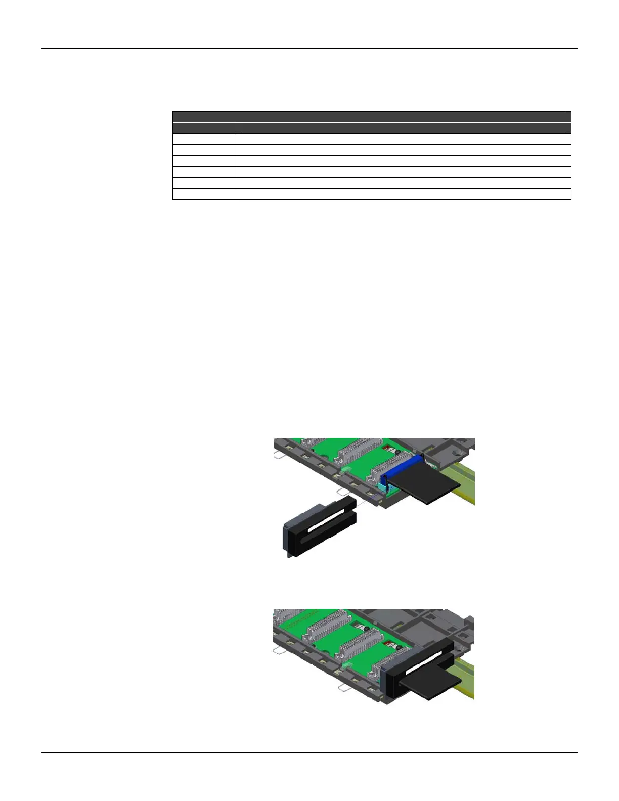
Flat cables protector (connector cap)
To meet the EMC requirements an ESD protector has to be installed on the flat cables connection,
at right. In the following figure a flat cable protector is shown when it is being installed on the cable
connector.
Figure 3.81 - Installing the flat cables protector
The following figure shows the flat cable protector installed.
Figure 3.82 - Flat cable protector installed