Modules And Accessories
3.65
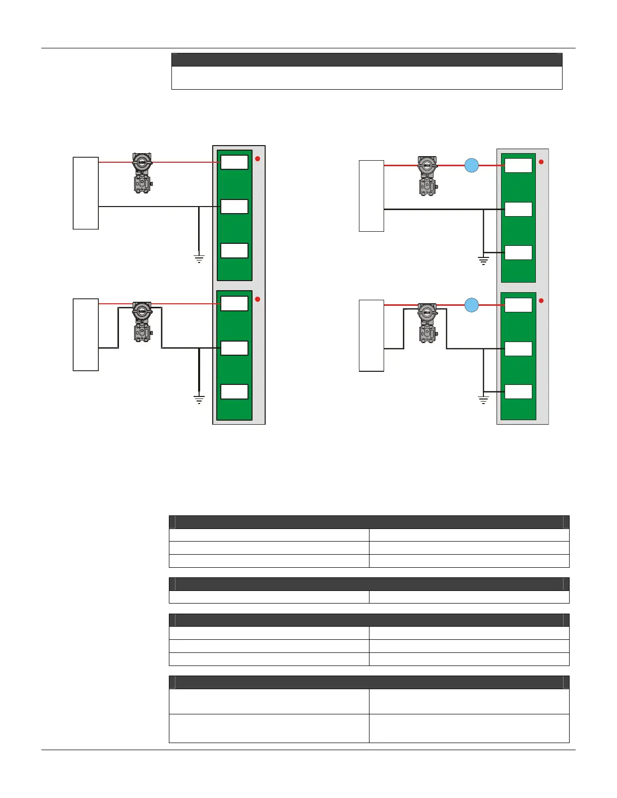
NOTES
To comply with the EMC standards, use shielded cables in signal inputs (ground the shield in the panel
only in one side of the cable).
The user can mark these labels if the input is set for current or internally set for voltage. (This refers
to the shunt position).
2B
3B
DC
PS
2A
DC
PS
3A
+
+
-
-
Ligação
a 2 fios
PS-AC-R.
PS302P.
ou
Fonte
Externa.
10A
10B
Ligação
a 4 fios
PS-AC-R.
PS302P.
ou
Fonte
Externa.
2B
3B
DC
PS
2A
DC
PS
A
3A
+
+
-
-
Ligação
a 2 fios
PS-AC-R.
PS302P.
ou
Fonte
Externa.
10A
10B
A
Ligação
a 4 fios
PS-AC-R.
PS302P.
ou
Fonte
Externa.
M-401-R M-401-DR
Figure 3. 39 - External Connection
Observation: In the picture above, the Ammeter for the M-401-DR is not mandatory
Technical Specifications
ARCHITECTURE
Number of inputs 8
Number of groups 1
Number of points per group 8
ISOLATION
Channel for Bus Isolation up to 1500 Vrms
INTERNAL SOURCE
Supplied by the IMB bus 5 Vdc @ 320 mA maximum
Total Maximum Dissipation 1.6 W
Power Supply Indicator Green LED
INPUTS
Linear measuring range
M-401-R/M-401-DR: 0-20 mA, 4-20 mA,
0-5V, 1-5 V, 0-10 V, ± 10 V.
Typical Input impedance
M-401-R/M-401-DR: 1 MΩ for voltage input
250 Ω for current input