LC700 – User’s Guide
3.86
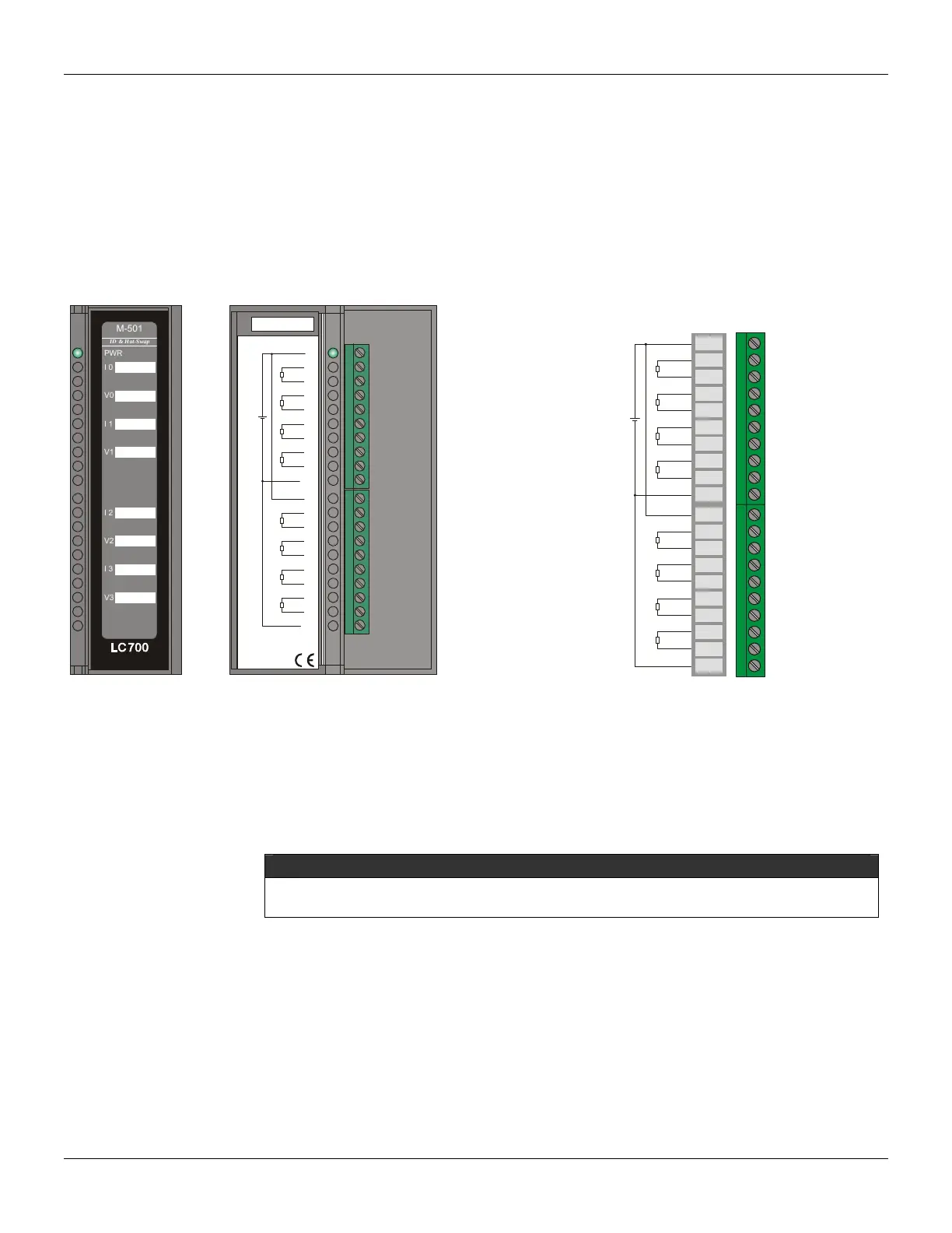
M-501 - Analog Output Module – Voltage / Current
(Supports Hot Swap and Device ID)
Part Number
M-501 (4 Current and 4 Voltage Analog Outputs)
Description
This module has 4 analog outputs, 0-3. Each analog output is available in the terminal in current and
voltage. Current outputs can be individually configured on ranges of 0-20 mA or 4-20 mA. Voltage
output ranges are: +/-10 V, 0-10 V, +/-5 V, 0-5 V and 1-5 V.
501/46 - 4 Analog Outputs 0-20mA, 4-20mA, 0-5V, 1-5V, 0-10V,±10V
PWR
PWR
GND
GND
I 0
V0
I 1
V1
I 2
V2
I 3
V3
1A
2A
3A
4A
5A
6A
7A
8A
9A
10A
1B
2B
3B
4B
5B
6B
7B
8B
9B
10B
+
-
+
-
+
-
+
-
+
-
+
-
+
-
+
-
I 0
V0
I 1
V1
V2
I 2
I 3
V3
smar
PWR
M-501
ID & Hot-Swap
smar
1A
2A
3A
4A
5A
6A
7A
8A
9A
10A
1B
2B
3B
4B
5B
6B
7B
8B
9B
10B
PWR
PWR
GND
GND
I 0
V0
I 1
V1
I 2
V2
I 3
V3
+
-
+
-
+
-
+
-
+
-
+
-
+
-
+
-
Figure 3. 57 - Current and Voltage Analog Output Module M-501 Figure 3. 58- External Connection
The signal output range for the output channels is set in the CONF700 (zero) and through the Dip
Switches (span) of the module.
DipSwitch 1 - UP Side: Configure the Group of Ranges of Channel 0 (I0/V0)
DipSwitch 2 - UP Side: Configure the Group of Ranges of Channel 1 (I1/V1)
DipSwitch 1 - DOWN Side: Configure the Group of Ranges of Channel 2 (I2/V2)
DipSwitch 2 - DOWN Side: Configure the Group of Ranges of Channel 3 (I3/V3)
NOTE
To comply with the EMC standards, use shielded cables in signal inputs (ground the shield in
the panel only in one side of the cable) and cables less then 30 meters for power source inputs.