LC700 – User’s Guide
3.110
Basic Installation Steps
9 Set the internal jumper (J1) to use internal or external power supply. To remove the circuit
board from the plastic Module push with moderate pressure each tab (top and bottom)
close to the grids, while forcing to separate the box from the front plastic panel.
9 Decide which RS asynchronous interface is going to be used. Configure Switch #1 (see
table below.)
9 Find out the working baud rate and configure Switch #2 (high or low baud rate range) then
turn on only one of the switches between #4 and #8.
9 Determine the necessity to work with point-to-point or multi-drop connection and define all
necessary cable, and then make sure the repeat Switch#2 is correctly configured on each
OPT-700 converter.
9 Make all connections and start the system. Follow the signal by the Rx and Tx LEDs on the
front panel. They will blink according to the data across the fiber line.
9 If there are any problems go to the “Troubleshooting” section of this Manual.
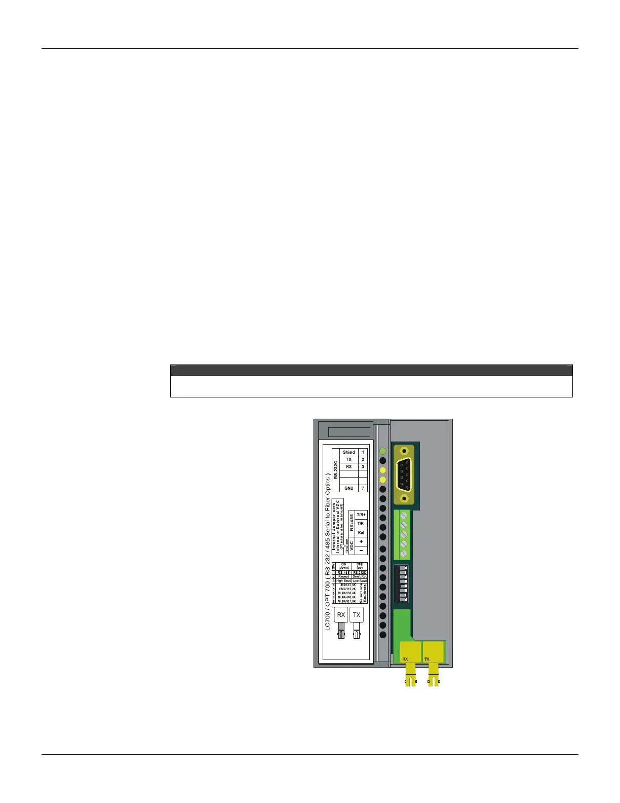
Front Panel Overview
The Figure below shows the OPT-700 Module with the front cover opened. From top to bottom we
can see the DB9 connector for the EIA-232-C, the 5-position terminal for the EIA-485 and external
power supply, 8 DIP switches for configuration, and finally the fiber optic receiver and transmitter.
NOTE
If the connection with the DB9 port is permanent, the DB9-EXT cable must be used to allow the
panel to be opened.
12345678
Figure 3.68 – Overview of the front panel