LC700 Architecture
2.15
Improving Signal Ground of LC700 (R-700-4A)
Besides the fact that the racks of the LC700 system are connected by flat cables for signal and
power transportation, it is possible to occur some fading in the signal ground for applications that
make use of many modules. A solution to keep the signal ground stable and the system more
immune to electrical noises is to add an extra wire between racks.
These wires should follow the flat cable path to avoid ground loops. Wire must be strained and have
a diameter of at least the AWG18.
For adjacent racks, use the “extending connector” placed on its left side. Obviously, it is possible to
have a system with adjacent and non-adjacent racks.
NOTES
1- The Rack containing the CPU-Module must be set with address “0”, always.
2- All other Racks can have any address from 1 to14.
3- Addresses can NOT be repeated in the same LC700 system.
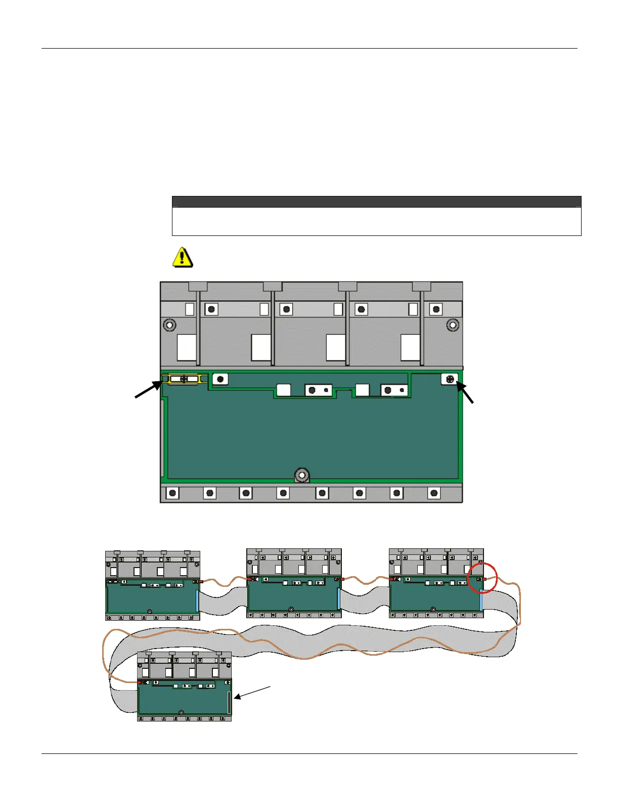
NOTE: Always use the Terminator Board, T-700, in the last rack.
The Racks
Signal
Ground
Signal
Ground
Figure 2.25 - A Rack showing points to connect the Signal Ground wire.
Non-adjacent Racks
Terminator
Board
Figure 2.26 - Shows how the Signal Ground cable is connected between Racks