Modules And Accessories
3.59
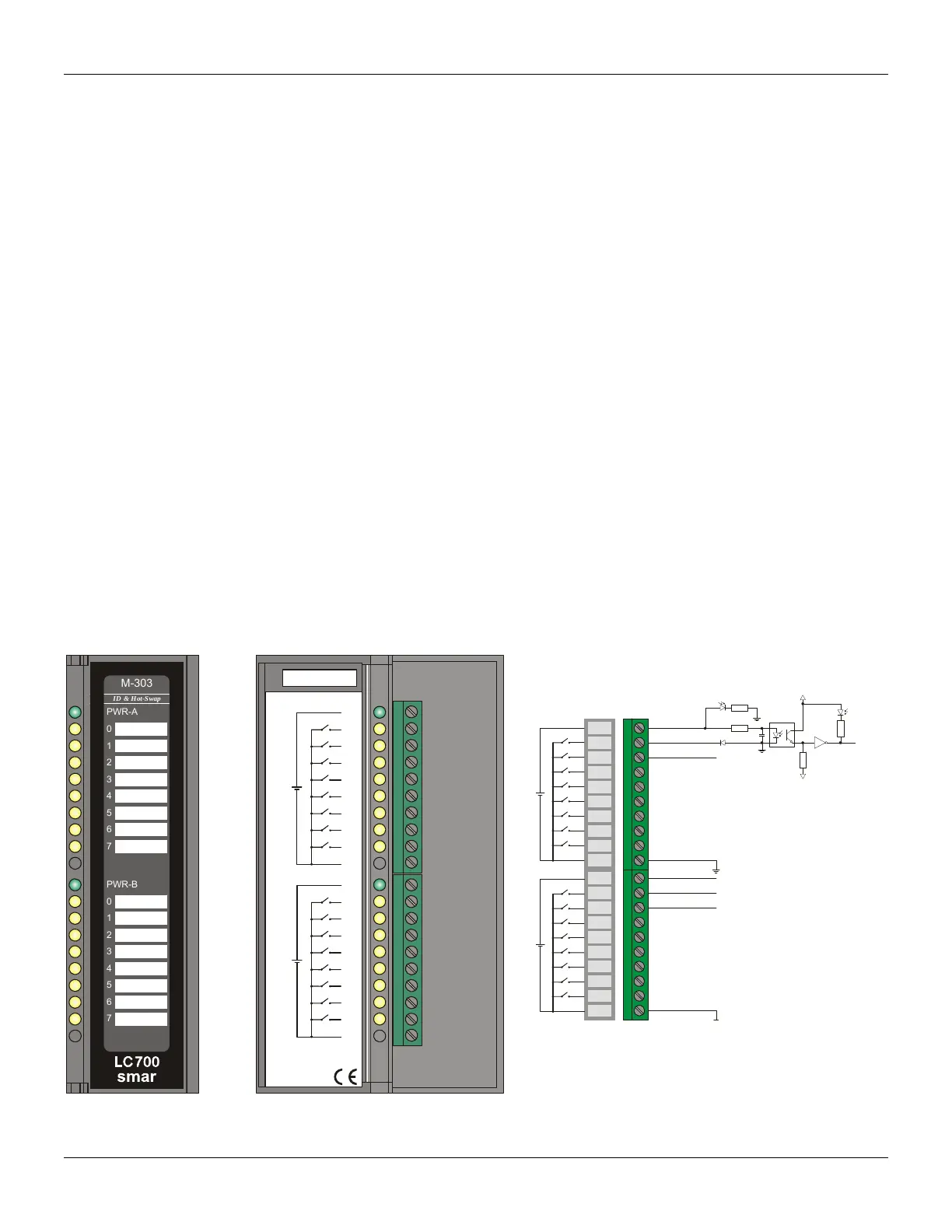
M-302/M-303 - Pulse Input Module – Low / High Frequency - DC
(Supports Hot Swap and Device ID)
Part Number
M-302 (2 groups of 8 24 Vdc pulse inputs 0-100 Hz).
M-303 (2 groups of 8 24 Vdc pulse inputs 0-10 KHz)
Description
These modules have two groups of 8 inputs to count pulses and to be accumulated until the CPU
module can read them. After the CPU reading, each individual counter will be cleared. The
hardware will reset to prevent the loss of any input pulse during this acquisition process.
The ACC Block was especially designed to be used with modules M-302 and M-303 to accumulate
input pulses from an external source. Usually one of the module inputs is connected to the IN input
of the ACC block.
During the control cycle these modules accumulate pulses in a local register in their circuit. At the
end of every control cycle the CPU reads the total accumulated value and automatically clears the
internal register for the next cycle (avoiding capacity overload). When the logic control is executed,
the ACC block generates an integer number representing the number of pulses accumulated. It then
adds them to an internal accumulator TOT_L and TOT_H. This accumulator is shared as outputs of
the ACC block.
Values accumulated in TOT_L and TOT_H are moved to the registers MEM_L and MEM_H.
Contents of TOT_L and TOT_H are cleared.
M-302 is an indicator to count frequencies from 0 to 100 Hz and may be controlled by a mechanical
relay contact or reed-switch. An internal filter has a cutoff frequency at approximately 200 Hz
M-303 is used to count pulses from a higher frequency source that will not generate bouncing during
switching. These modules can read from 0 to 10 KHz. An internal filter has cut off frequencies at
around 20 KHz to eliminate high frequency noise.
PWR-A
PWR-B
GND-A
GND-B
303/42 - 2 groups of 8 High speed pulse inputs - Sink
1A
2A
3A
4A
5A
6A
7A
8A
9A
10A
1B
2B
3B
4B
5B
6B
7B
8B
9B
10B
M-101
smar
PWR-A
1
2
3
4
5
6
7
PWR-B
0
1
2
3
4
5
6
7
smar
0
M-303
ID & Hot-Swap
R
R
cc
Yellow
Green
IM
In1A
In2A
In1B
Vext1
Vext2
In2B
1A
2A
3A
4A
5A
6A
7A
8A
9A
10A
1B
2B
3B
4B
5B
6B
7B
8B
9B
10B
PWR-A
PWR-B
GND-A
GND-B
Figure 3.34 - Pulse Counter Module M-303
Figure 3.35- External Connection