Modules And Accessories
3.7
OTHER LEDs
RUN Green LED indicates that program is running
HOLD Yellow LED indicates that program is in hold
FORCE
Red LED indicates that inputs and/or outputs
are in the force mode.
Rx (Yellow LED)
Tx (Green LED)
Rx - Displays Modbus Communication receipt
(EIA-485)
Tx – Displays Modbus Communication
transmission (EIA-485)
Rx (Yellow LED)
Tx (Green LED)
Rx - Displays Modbus Communication receipt
(EIA-485)
Tx – Displays Modbus Communication
transmission (EIA-485)
DIMENSIONS AND WEIGHT
Dimensions (W x D x H)
39.9 x 137.0 x 141.5 mm ;
(1.57 x 5.39 x 5.57in)
Weight 0.286 kg
CABLES
One Wire 14 AWG (2 mm
2
)
Two Wires 20 AWG (0.5 mm
2
)
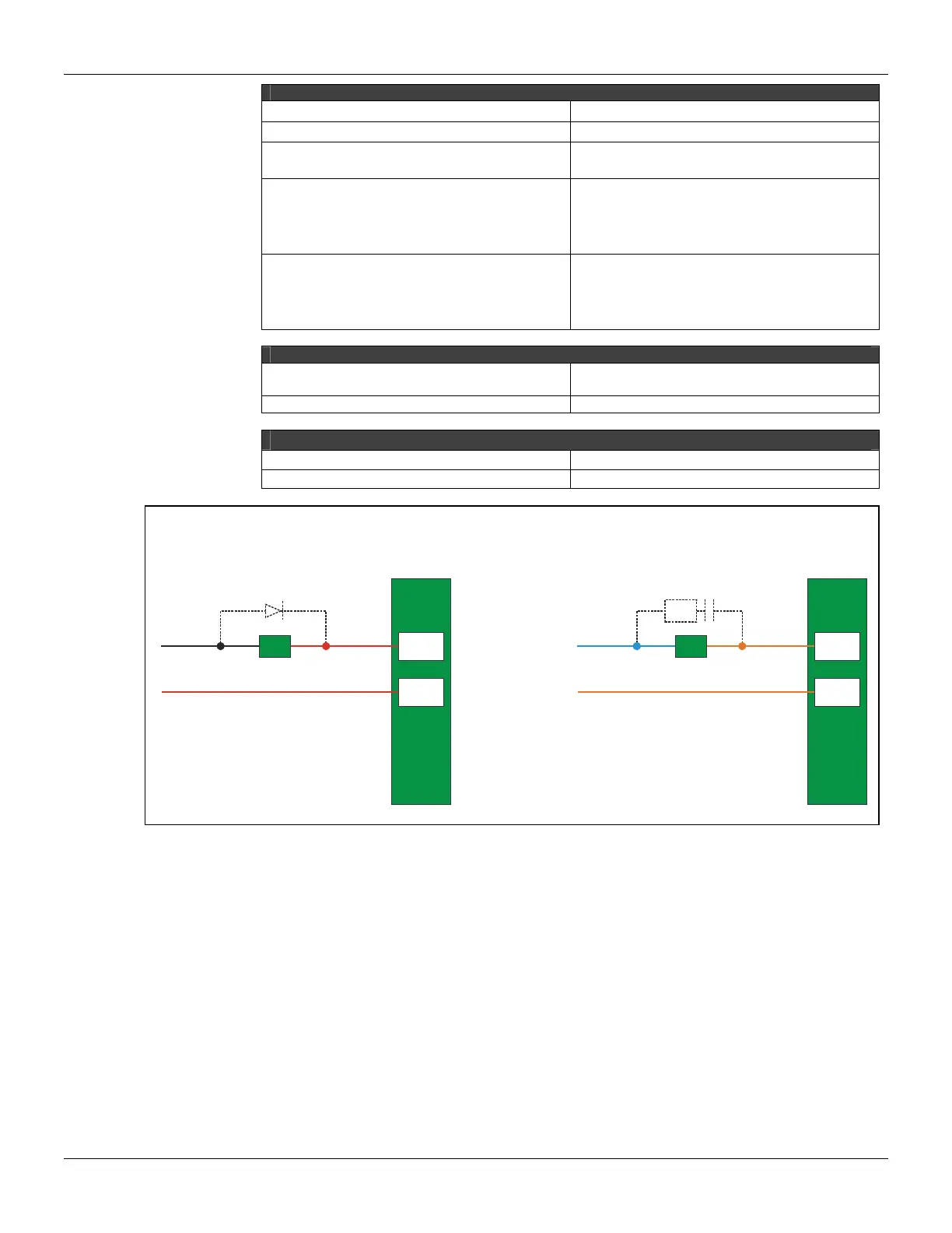
Note
To increase service of life of your relays and to protect your modules from reverse voltage damages, externally
connect a clamping diode in parallel with each inductive DC load or externally connect an RC snubber circuit in
parallel with each inductive AC load.
7 B
8 B
-
+
A
LoadD
Load
7 B
8 B
RC
N
L
Communication Channels
The CPU-700-C3 has 3 communication channels that supply the user with 3 independent channels
(ports) identified as P1 (EIA-232), P2 (EIA-485) and P3 (EIA-485).
All of the 3 channels can be used at the same time with the following features:
¨ P1 (RS-232- C) is for programming and monitoring, point-to-point short connections.
¨ P2/P3 (RS-485) is for programming and monitoring, point-to-point or multi-drop in long distance
industrial connections.
¨ Any of the ports can be connected to the ENET-700/ENET-710 (Ethernet/Serial) converter
module.
In one Network it is possible to have up to 31 CPU-700 modules. In order to make the correct
communication, each CPU-700 module must have an unique MODBUS ID (address) and a
baudrate for P1 (Modbus) and other baudrate for P2 and P3 (Modbus). Modbus baudrates are
configurable by software throughout the use of CONF700.