LC700 – User’s Guide
2.4
IMPORTANT
Remember to leave a space in the DIN rail to install the DF91 and the grounding terminal at rack’s left side.
Installing racks in the DIN rail
IMPORTANT
Before installing the rack on DIN rail, connect the flat cable to rear’s connector (E) if you will connect this rack
to another at left. After connected to the DIN rail is not possible place the flat cable on the rear’s rack without
remove it.
1. Use a screwdriver (or your fingers) to pull the clips down.
2.
Place the back of the rack on the top of the DIN rail edge.
3. Accommodate the rack on the DIN rail and push the clips up. You will hear a click sound
when they lock properly.
4. Set the correct address for the DF93 rack using its rotating switch (J).
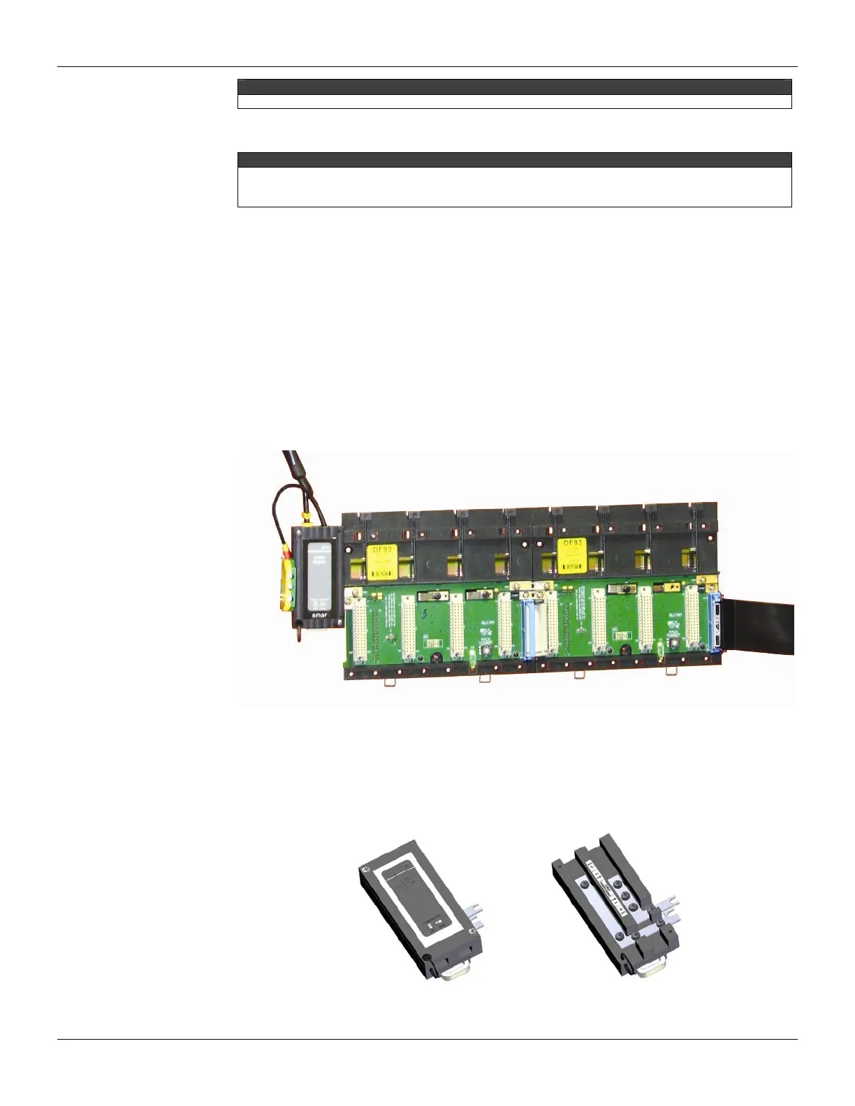
Connection between adjacent racks
1. The adjacent cards to the joining part, between the racks, must be removed allowing
access to this operation (racks’s third slot, at left and slot 0 of rack, at right).
2. Connect the two racks using FC-700-0 flat cable. This flat cable should already be
connected to the connector on the rear’s rack at right. And then, connect it to the top
connector (N) of the rack at left.
3. Connect the two racks to the power connectors (L and M), moving them with a screwdriver
and fixing with screws. Loose the screws only the suficient avoiding them from falling when
making the connection. See the next figure.
Figure 2.4 - Connection between adjacent racks
Using the DF91
The DF91 must be installed at left side of each row of racks, to meet the requeriments of EMC
standards even if no expansion of power
.
For further details about DF91 installation, refer to “Expanding the system’s power supply
– DF90 and DF91” topic.
Figure 2.5 - DF91 details