LC700 – User’s Guide
3.82
OUTPUTS
Vac Range
20-250 Vac (M-120/M-121/M-122/M-124/M-
125/M-126)
Vdc Range
20-125 Vdc (M-120/M-121/M-122/M-124/M-
125/M-126)
Maximum Current for 30 Vdc/250 Vac
5A (resistive); 2A (inductive) (M-120/M-121/M-
122/M-124/M-125/M-126)
Minimum Current
10 mA (M-120/M-121/M-122/M-124/M-125/M-
126)
Initial contact resistance maximum
30 m
Ω (M-120/M-121/M-122/M-124/M-125/M-
126)
Status display Yellow LED
Indicator Logic ON if the relay’s coil is active
Leakage
500
μA @ 100 Vac (M-120/M-121/M-122)
None (M-124/M-125/M-126)
Over load protection per output Should be provided externally
SWITCHING INFORMATION
RC Protection Circuit
62 Ω in series with 0.01 μF (M-120/M-121/M-
122)
None (M-124/M-125/M-126)
Operate Time
10 ms Maximum (M-120/M-121/M-122/ M-
124/M-125/M-126)
Release Time
10 ms Maximum (M-120/M-121/M-122/ M-
124/M-125/M-126)
ELECTRICAL SERVICE LIFE
Switching Cycles
100.000 minimum operations @ maximum
current (M-120/M-121/M-122/ M-124/M-
125/M-126)
DIMENSIONS AND WEIGHT
Dimensions (W x D x H)
39.9 x 137.0 x 141.5 mm;
(1.57 x 5.39 x 5.57 in)
Weight 0.305 kg
CABLES
One Wire 14 AWG (2 mm
2
)
Two Wires 20 AWG (0.5 mm
2
)
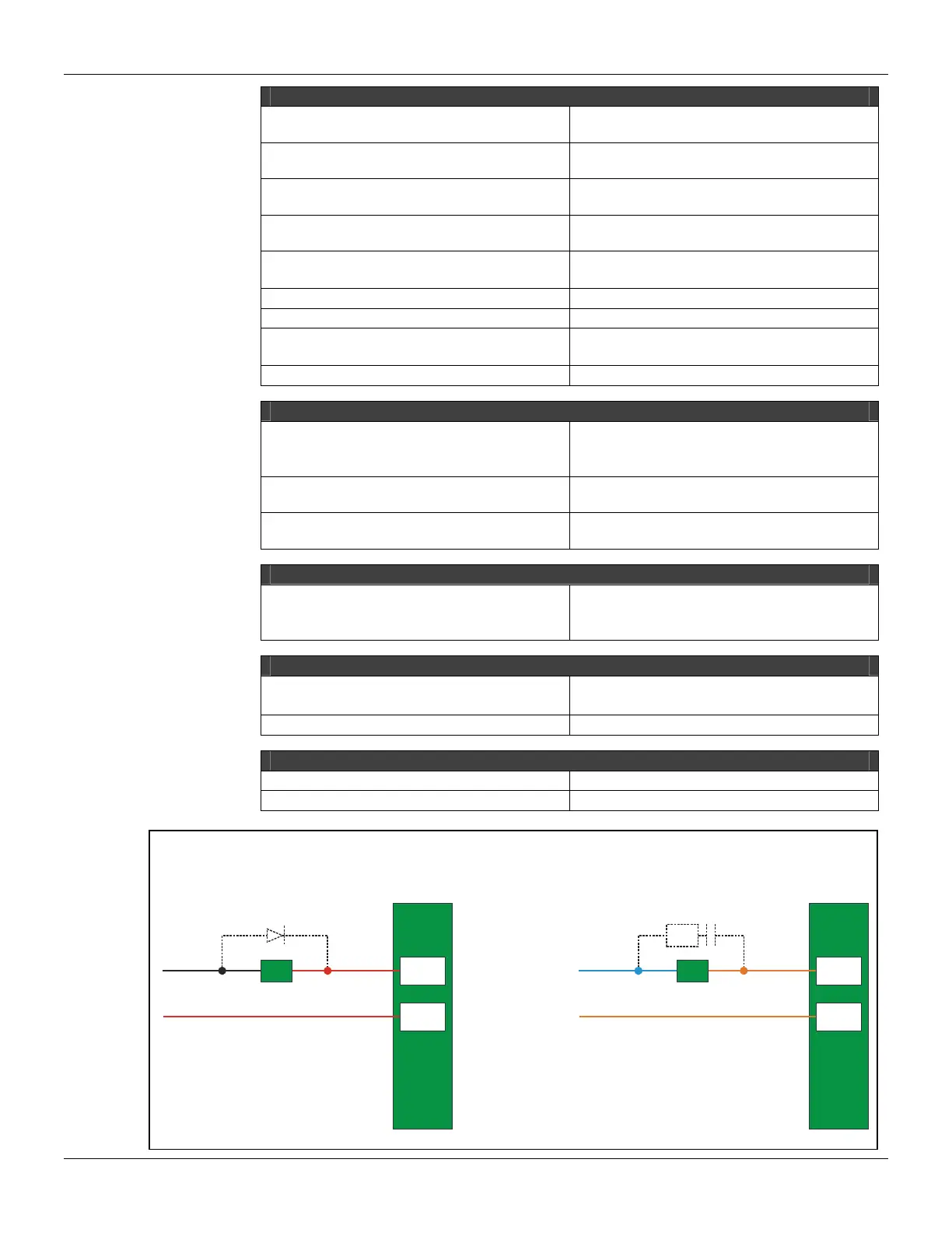
Note
To increase service of life of your relays and to protect your modules from reverse voltage damages, externally
connect a clamping diode in parallel with each inductive DC load or externally connect an RC snubber circuit in
parallel with each inductive AC load.
2 B
3 B
-
+
A
LoadD
Load
2 B
3 B
RC
N
L