Modules And Accessories
3.93
Block Type Description LC700 Block
MDI
Multiple Discrete Inputs
CODD
MDO
Multiple Discrete Outputs
CIDD
MAI
Multiple Analogic Inputs
COAD
MAO
Multiple Analogic Outputs
CIAD
Connecting FB-700 to LC700
Before connecting or disconnecting the FB-700 from the LC700 backplane, please be sure that the
LC700 power is OFF.
LEDs behavior
The FB-700 red and yellow LEDs indicate errors and warnings as described in the following tables:
- Yellow LED
Always on
FB-700 is saving nonvolatile data. After finishing this operation the yellow
LED will be turned off.
Blinking at 1s
rate
LC700 and FB-700 do not have the same configuration parameters. Please,
check both SYSCON and LC700 configurations to ensure that the number
of function blocks and FB700 TAG are the same.
Blinking at 3s
rate
There is a new configuration in the dual port memory, but the LC700 does
not check it.
Blinking at 5s
rate
There is a new configuration in the dual port memory without any MIO
function block.
- Red LED
Always on
A critical error happened and FB-700 is in a permanent failure state. FB-700
must be reset.
Blinking at 1s
rate
LC700 is not accessing FB-700. Possible causes are LC700 is not running
properly, FB-700 is not present in LC700 configuration or rack addressing is
wrong.
FB-700 is developed to communicate with fieldbus devices through the FOUNDATION fieldbus
TM
H1 channel.
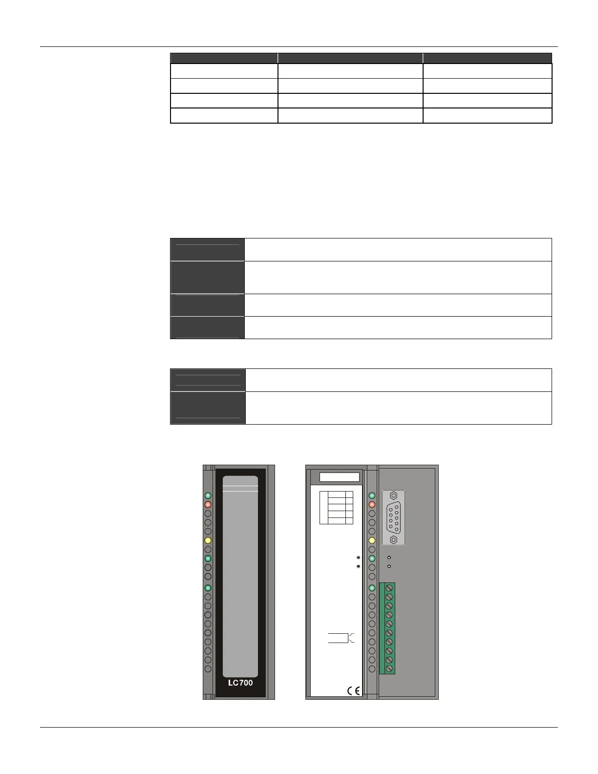
smar
+5VDC+5VDC+5VDC+5VDC
FAILFAIL
SAVINGSAVING
232232
FF0 (H1)FF0 (H1)
FB-700FB-700
ID & Hot-Swap
LC700/FB-700 Fieldbus Module
PGND
TX
1
2
3
7
8
RS-232
RX
GND
5V
0,5A
FF0 (H1)
1B
RESET
FACTORY INIT
2B
3B
4B
5B
6B
7B
8B
9B
10B
Figure 3. 61 - Fieldbus Module FB-700