LC700 – User’s Guide
3.14
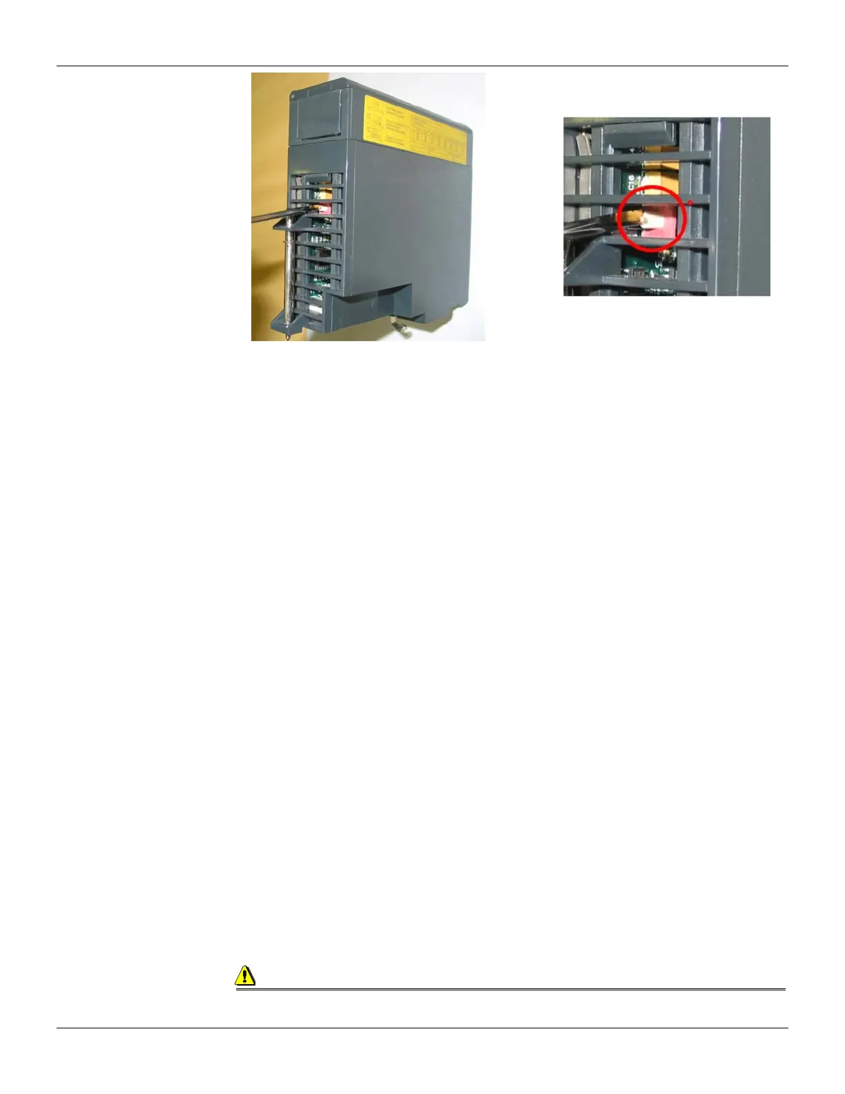
Figure 3.6 - Locating the CPU-700 Rotary Switch. Detail: The Rotary Switch
CPU-700 with 3 MODBUS RTU Channels
When the CPU-700 is used as a regular CPU, it means that no Remote I/O module is being used.
Also, either P3 as P1 and P2 may act as MODBUS/RTU channels. Note that none of them can act
as a MODBUS master.
P1, P2 and P3 are independent MODBUS/RTU slave channels. They can be used at the same time.
P1 is recommended for point-to-point connections whereas P2 and P3 may be used in two different
networks (master and slave) to increase accessibility of the CPU through two computers (masters)
or in a redundant architecture where the user can alternate between the channels in a failure
situation.
Settings:
The rotary key must be in the position 8.
One MODBUS ID set for P1, P2 and P3 (set on CONF700).
The P1, P2 and P3 baud rates are set on CONF700.
CPU-700 master in a remote I/O System
The CPU-700 can be also a master in a Remote I/O system. This means that the CPU-700 acts as
the main processing unity acquiring data from the Remote I/O modules in its own IMB and also from
any remote I/O connected to it.
In this case P3 is completely dedicated to Remote I/O communication data. P1 and P2 are slave
MODBUS/RTU independent channels. P1 is used for point-to-point applications whereas P2 may be
used in a multi drop network.
Settings:
The rotary Switch must be in the position 0.
One ID MODBUS for P1 and P2 set on CONF700.
P1 and P2 baud rates are set on CONF700.
P3, the RIO channel, has its own dedicated baud rate set through the frontal dip switch.
Factory Init
The user can carry out a procedure to make the CPU-700 to assume its factory configuration. This
procedure is called factort-init.
To do it:
1. Remove the CPU-700 from the power supply.
2. Put the Rotary Switch on the position 7
3. Put the Dip Switch 4 in the default position
4. Connect the CPU-700 to the power supply and wait until the HOLD led starts to blink
5. Remove the CPU-700 from the power supply.
6. Set the rotary switch
Observation
After the Factory Init procedure, the user must set the Rotary Switch when a new download is
done.