DCR-PC101/PC101E
5-36
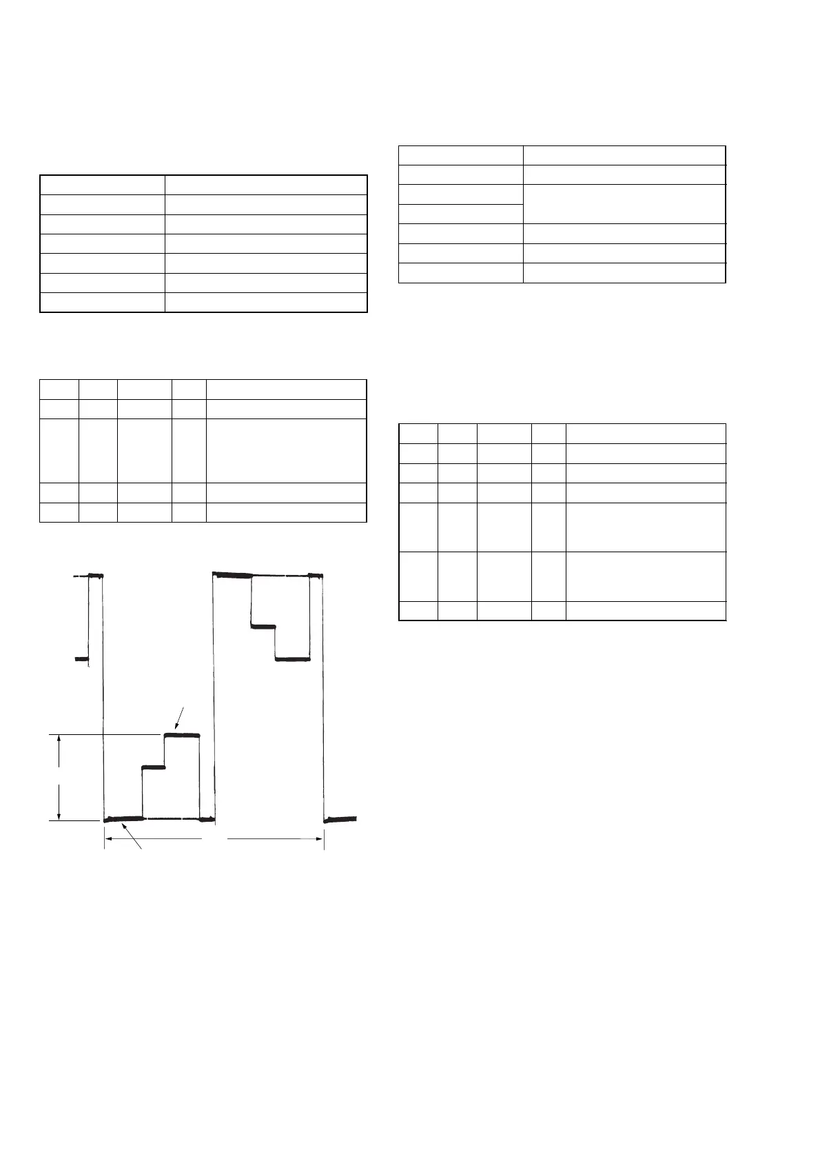
4. Contrast Adjustment (VC-284 board)
Set the video signal level for driving the LCD to the specified
value.
If deviated, the EVF screen image will be blackish or saturated
(whitish).
Mode CAMERA
Subject Not required
Measurement Point Pin 4 of CN1006 (EVF_VG)
Measuring Instrument Oscilloscope
Adjustment Page C
Adjustment Address 58
Specified Value A = 2.40 ± 0.1 Vp-p
Note: Check that the data of page: 0, address: 10 is “00”.
Adjusting method:
Order Page Address Data Procedure
1 0 01 01
2C 58
Change the data and set the
voltage (A) to the specified
value. (The data should be
“00” to “7F”)
3 C 58 Press PAUSE button.
4 0 01 00
5. White Balance Adjustment (VC-284 board)
Correct the white balance.
If deviated, the EVF screen color cannot be reproduced.
Mode CAMERA
Subject Not required
Measurement Point Check on EVF screen
Measuring Instrument
Adjustment Page C
Adjustment Address 56, 57
Specified Value EVF screen must not be colored
Note 1: Check that the data of page: 0, address: 10 is “00”.
Note 2: Check the white balance only when replacing the fol-
lowing parts. If necessary, adjust them.
1. LCD panel
2. Light induction plate
3. IC4201
Adjusting method:
Order Page Address Data Procedure
1 0 01 01
2 C 56 8D Press PAUSE button.
3 C 57 73 Press PAUSE button.
4
Check that the EVF screen is
not colored. If not colored,
proceed to step 6.
5C
Change the data so that the
EVF screen is not colored.
(Note 3)
6 0 01 00
Note 3: To write in the non-volatile memory (EEPROM), press
the PAUSE button each time to set the data.
A: Between the pedestal and 3 steps peak
Fig. 5-1-16
3 steps peak
Pedestal
A
2H
56
57