DCR-PC101/PC101E
5-34
1. VCO Adjustment (VC-284 board)
Set the VCO free-run frequency. If deviated, the EVF screen will
be blurred.
Mode CAMERA
Subject Not required
Measurement Point Pin 5 of CN1006 (EVF_VCO)
Measuring Instrument Frequency counter
Adjustment Page C
Adjustment Address 51, 52
Specified Value f = 15734 ± 30 Hz (NTSC)
f = 15625 ± 30 Hz (PAL)
Note 1: Check that the data of page: 0, address: 10 is “00”.
Note 2: NTSC model: DCR-PC101
PAL model: DCR-PC101E
Adjusting method:
Order Page Address Data Procedure
1 0 01 01
2C 51
Change the data and set the
frequency (f) to the specified
value.
3 C 51 Press PAUSE button.
4C 51
Read the data and this data is
named D
51
.
5
Convert D
51
to decimal
notation, and obtain D
51
’.
(Note 3)
6
Calculate D
52
’ using
following equations.
(decimal calculation)
D
52
’ = D
51
’ + 25 (NTSC model)
D
52
’ = D
51
’ – 25 (PAL model)
7
Convert D
52
’ to a hexadeci-
mal number, and obtain D
52
.
(Note 3, 4)
8C 52D
52
Press PAUSE button.
9 0 01 00
Note 3: Refer to table 5-4-1. “Hexadecimal-decimal conversion
table”
Note 4: If D
52
’ > 255, then D
52
= FF (NTSC model)
If D
52
’ < 0, then D
52
= 00 (PAL model)
1-4. COLOR ELECTRONIC VIEWFINDER
SYSTEM ADJUSTMENTS
Before perform the viewfinder system adjustments, check the data
of page: 0, address: 10 is “00”.
If not, select page: 0, address: 10, and set the data “00”.
Note 1: Taken an extreme care not to destroy the liquid crystal
display module by static electricity when replacing it.
Note 2: Perform the following data setting before the viewfinder
system adjustments.
1) Select page: 3, address: C4, and set data: 67.
2) Select page: 3, address: C5, and set data: 01.
Reset the data after completing adjustment.
1) Select page: 3, address: C4, and set data: 00.
2) Select page: 3, address: C5, and set data: 00.
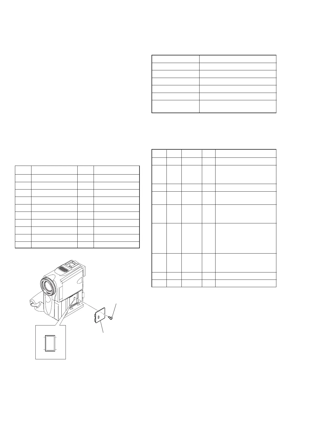
[Adjusting connector]
Most of the measuring points for adjusting the viewfinder system
are concentrated in CN1006 of the VC-284 board.
Connect the Measuring Instruments via the CPC-6 flexible jig (J-
6082-370-B) and CPC-6 terminal board jig (J-6082-371-A).
The following table shown the Pin No. and signal name of CN1006.
Pin No.
Signal Name
Pin No.
Signal Name
1 FLASH_UNREG 2 D_2.8V
3 EVF_LED_DA 4 EVF_VG
5 EVF_VCO 6 GND
7 MD2 8 XCS_MC_FLASH
9 XINIT 10 XCS_ST_IMAGE_IC
11 DRUM_ON 12 FRRV
13 REC_CRRT1 14 REC_CRRT0
15 REG_GND 16 HI_XRESET
17 SWP 18 RF_IN
19 GND 20 RF_MON
Fig. 5-1-14
CPC lid
CN1006
21
20 19
Screw