DCR-PC101/PC101E
5-50
3-3. SERVO AND RF SYSTEM ADJUSTMENTS
Before perform the servo and RF system adjustments, check that
the specified values of “66MHz/54MHz Origin Oscillation Ad-
justment” of “1-3. CAMERA SYSTEM ADJUSTMENTS” is sat-
isfied.
Check that the data of page: 0, address: 10 is “00”.
If not, select page: 0, address: 10, and set the data “00”.
Adjusting Procedure:
1. CAP FG duty adjustment
2. PLL f
0
& LPF f
0
Pre-adjustment
3. Switching position adjustment
4. AGC center level and APC & AEQ adjustment
5. PLL f
0
& LPF f
0
final adjustment
1. CAP FG Duty Adjustment (VC-284 board)
RadarW
RadarW
RadarW
Set the CAP FG signal duty cycle to 50% to establish an appropri-
ate capstan servo. If deviated, the uneven rotation of capstan and
noise can occur in the LP mode.
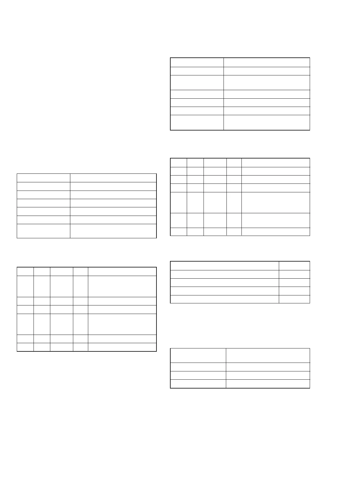
Mode VTR stop
Signal No signal
Measurement Point Displayed data of page: 3, address: 03
Measuring Instrument Adjusting remote commander
Adjustment Page C
Adjustment Address 16
Specified value The data of page: 3, address: 03 is
“00”
Note 1: Check that the data of page: 0, address: 10 is “00”.
Adjusting method:
Order Page Address Data Procedure
1
Close the cassette compart-
ment without inserting
cassette.
2 0 01 01
3 3 01 1B Press PAUSE button.
43 02
Check the data changes in
the following order
“1B” t “2B” t “00”
5 3 03 Check the data is “00”. (Note 2)
6 0 01 00
Note 2: If the data is “01”, adjustment has errors or the mecha-
nism deck is defective.
2. PLL f
0
& LPF f
0
Pre-Adjustment (VC-284 board)
RadarW
RadarW
RadarW
Mode VTR stop
Signal No signal
Measurement Point Displayed data of page: 3, address:
02 and 03
Measuring Instrument Adjusting remote commander
Adjustment Page C
Adjustment Address 1F, 20, 22, 29
Specified value The data of page: 3, address: 02 is “00”
The data of page: 3, address: 03 is “00”
Note 1: Check that the data of page: 0, address: 10 is “00”.
Adjusting method:
Order Page Address Data Procedure
1 0 01 01
2 C 21 DC Press PAUSE button.
3 3 01 30 Press PAUSE button.
43 02
Check the data changes to
“00” within 5 seconds.
(Note 2)
53 03
Check the data is “00”.
(Note 2, 3)
6 0 01 00
Note 2: If check is NG, select page: C, address: 21, set the fol-
lowing data, and press the PAUSE button, and repeat steps
3 to 5.
Setting data
When the data of page: C, address: 21 is “DC” E0
When the data of page: C, address: 21 is “E0” D8
When the data of page: C, address: 21 is “D8” E4
When the data of page: C, address: 21 is “E4” D4
The adjustment is defective, if the above procedure results in NG.
Note 3: If bit value of bit2, bit3, bit4, bit5 or bit6 is “1”, adjust-
ment has errors. For the error contents, see the follow-
ing table. (For the bit values, refer to “5-4. SERVICE
MODE”, “4-3. 3. Bit value discrimination”.)
Bit value of page: 3,
address: 03 data
Error contents
bit2 = 1 or bit 3 =1 PLL f
0
fine adjustment is defective
bit4 = 1 or bit 5 =1 PLL f
0
adjustment is defective
bit6 = 1 LPF f
0
adjustment is defective