DCR-PC101/PC101E
5-32
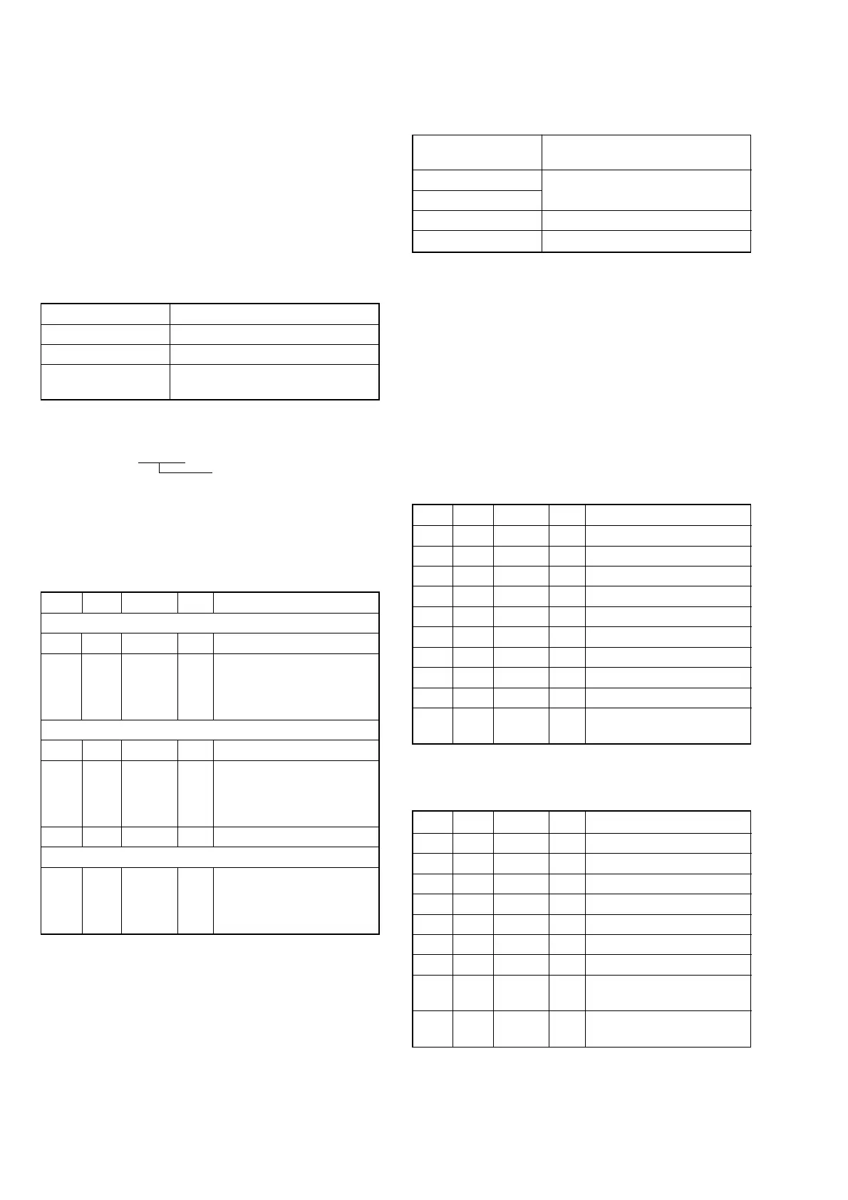
16. CCD Black Defect Adjustment
RadarW
RadarW
RadarW
Detect the black defect position of the CCD imager.
Subject Clear chart (All white)
(40 cm from the front of the lens)
Measurement Point Adjusting remote commander
Measuring Instrument
Adjustment Page 1E
Adjustment Address 20 to 2F
Note 1: If reading/writing data on pages 1E, set data: 01 to page:
0, address: 10, and then select pages E. By this data set-
ting, the pages 1E can be selected.
After the data reading/writing finished, return the data
on page: 0, address: 10 to “00”.
Note 2: Perform “Flange Back Adjustment” before this adjust-
ment.
Note 3: Check that the data of page: 6, address: 02 is “00”.
If not, turn the power of unit OFF/ON.
Switch setting
1) POWER .................................................................CAMERA
2) NIGHT SHOT.................................................................OFF
Adjusting method:
Order Page Address Data Procedure
1 0 01 01
26 2C01
36 9C01
4 6 90 50
5 6 91 01
6 6 92 00
7 6 93 01
8 6 01 79 Press PAUSE button.
9 6 01 8D Press PAUSE button. (Note 4)
10 6 02
Check the data changes to
“01”.
Note 4: The adjustment data will be automatically input to page:
1E, address: 20 to 2F.
Processing after Completing Adjustment:
Order Page Address Data Procedure
1 6 01 00 Press PAUSE button.
26 2C00
36 9C00
4 6 90 00
5 6 91 00
6 6 93 00
7 0 01 00
8
Turn OFF the main power
supply.
9
Perform “CCD Defect
Check”.
15. Steady shot Check
RadarWRadarWRadarW
Precautions on the Parts Replacement
There are two types of repair parts.
Type A ENC03JA
Type B ENC03JB
Replace the broken sensor with a same type sensor. If replace with
other type parts, the image will vibrate up and down or left and
right during hand-shake correction operations.
Precautions on Angular Velocity Sensor
The sensor incorporates a precision oscillator. Handle it with care
as if it dropped, the balance of the oscillator will be disrupted and
operations will not be performed properly.
Subject Not required
Measurement Point Displayed data of page: 1 (Note 1)
Measuring Instrument Adjusting remote commander
Specified value PITCH data: 2B00 to 4B00
YAW data: 2B00 to 4B00
Note 1: The right four digits of the page: 1 displayed data of the
adjusting remote commander.
1 :
XX : XX
Displayed data
Note 2: Check that the data of page: 0, address: 10 is “00”.
Switch setting
1) ZOOM ..................................................................... TELE end
2) STEADY SHOT (Menu setting) ....................................... ON
Checking method:
Order Page Address Data Procedure
PITCH sensor output check (SE201 of CF-089 board)
1 0 03 11
21
With the set in still state,
check that the displayed data
(Note 1) satisfies the PITCH
data specified value.
YAW sensor output check (SE202 of CF-089 board)
3 0 03 12
41
With the set in still state,
check that the displayed data
(Note 1) satisfies the YAW
data specified value.
5 0 03 00
Steady shot operation check
6
Shake the set vertically and
horizontally to check that the
steady shot function operates
normally.