DCR-PC101/PC101E
5-4
J-1 J-2
J-6
J-3
J-7 J-8
J-4 J-5
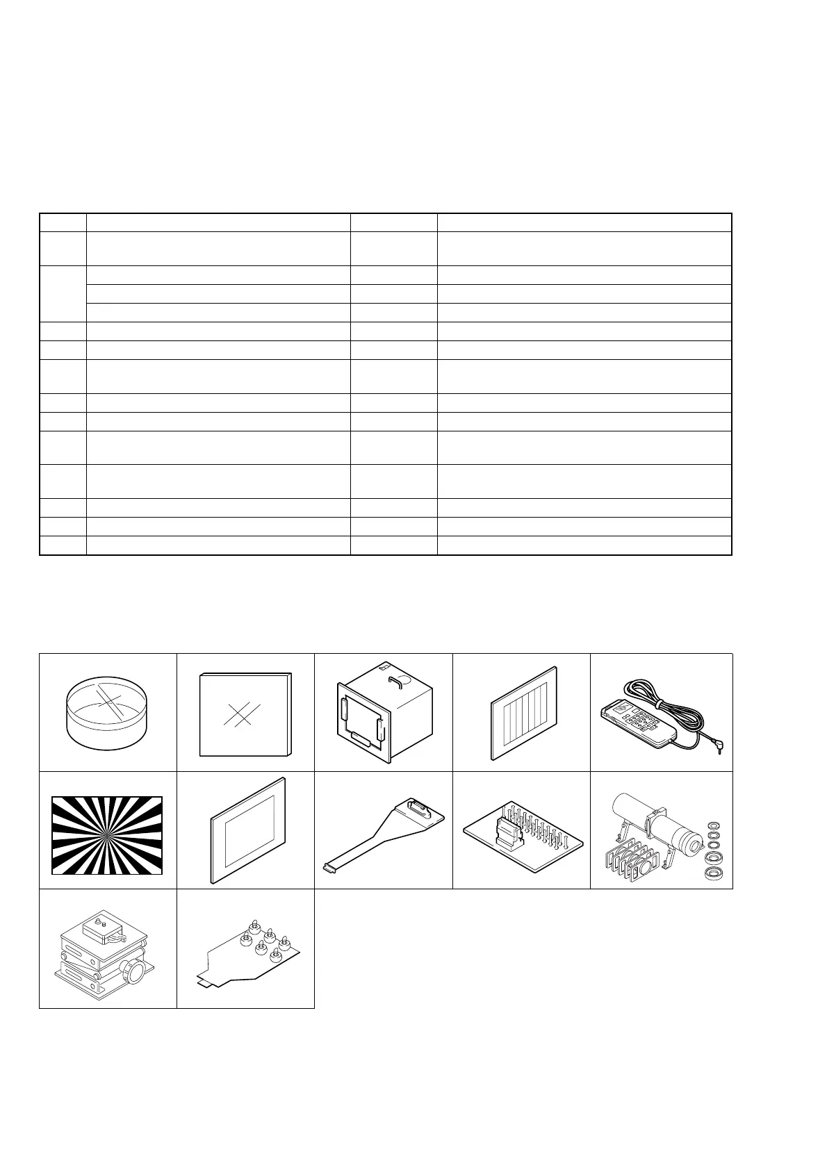
Fig. 5-1-1
J-9 J-10
J-11
Ref. No.
J-1
J-2
J-3
J-4
J-5
J-6
J-7
J-8
J-9
J-10
J-11
J-12
Name
Filter for color temperature correction (C14)
ND filter 1.0
ND filter 0.4
ND filter 0.1
Pattern box PTB-450
Color chart for pattern box
Adjustment remote commander (RM-95 upgraded).
(Note 1)
Siemens star chart
Clear chart for pattern box
CPC-6 flexible jig (Note 2)
CPC-6 terminal board jig
Mini pattern box
Camera table
CPC-jig for LCD panel
Parts Code
J-6080-058-A
J-6080-808-A
J-6080-806-A
J-6080-807-A
J-6082-200-A
J-6020-250-A
J-6082-053-B
J-6080-875-A
J-6080-621-A
J-6082-370-B
J-6082-371-A
J-6082-353-B
J-6082-384-A
J-6082-529-A
Usage
Auto white balance adjustment/check
White balance adjustment/check
White balance check
White balance check
White balance check
For checking the flange back
For adjusting the video section
For adjusting the color viewfinder
For adjusting the video section
For adjusting the color viewfinder
For adjusting the flange back
For adjusting the flange back
For adjusting the LCD system
5-1. CAMERA SECTION ADJUSTMENTS
1-1. PREPARATIONS BEFORE ADJUSTMENT (CAMERA SECTION)
1-1-1. List of Service Tools
• Oscilloscope • Color monitor • Vectorscope
• Regulated power supply • Digital voltmeter • Frequency counter
Note 1: If the micro processor IC in the adjustment remote com-
mander is not the new micro processor (UPD7503G-
C56-12), the pages cannot be switched. In this case, re-
place with the new micro processor (8-759-148-35).
Note 2: The old CPC-6 flexible jig (J-6082-370-A) is also us-
able.
J-12