DCR-PC101/PC101E
5-40
7. V-COM Adjustment (PD-166 board)
Set the DC bias of the common electrode drive signal of LCD to
the specified value.
If deviated, the LCD display will be move, producing flicker and
conspicuous vertical lines.
Mode CAMERA
Subject Not required
Measurement Point Check on LCD screen
Measuring Instrument
Adjustment Page C
Adjustment Address 63
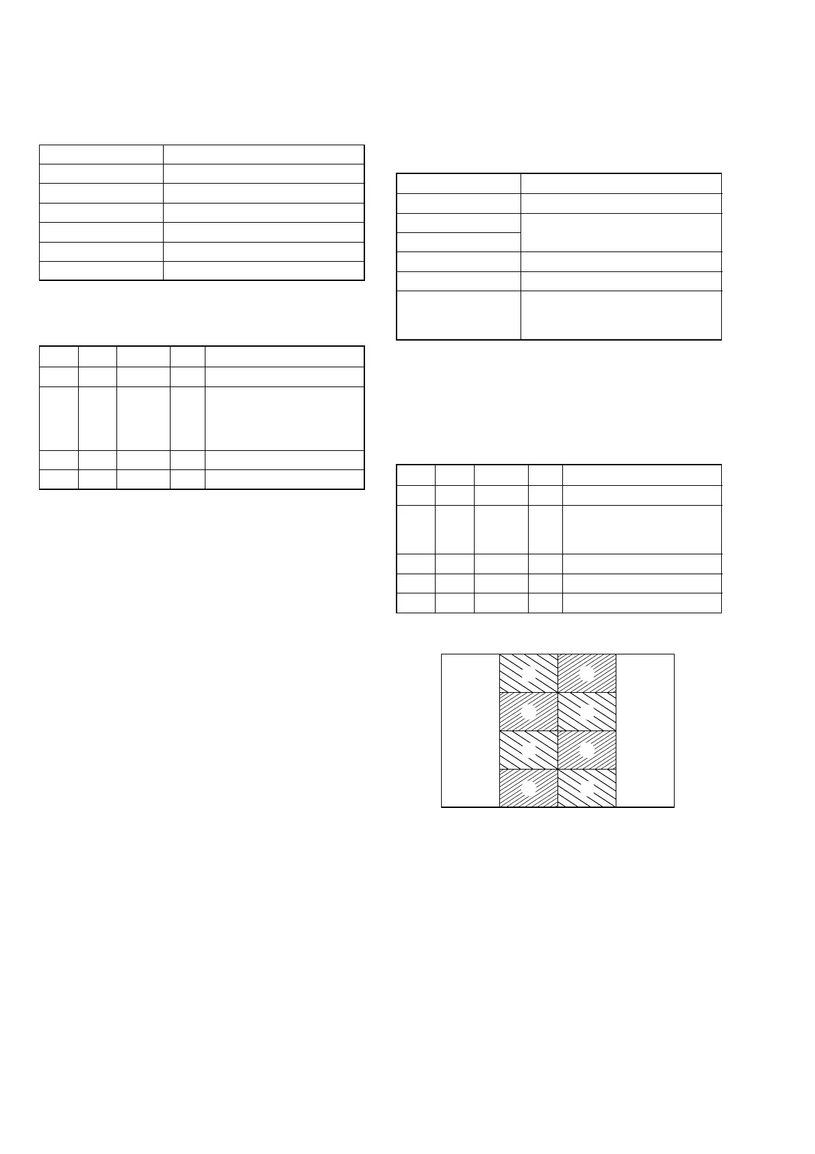
Specified Value The brightness difference between
the section-A and section-B is
minimum
Note 1: Perform “RGB AMP Adjustment”, “Black Limit Adjust-
ment”, “PSIG GRAY Adjustment”, “Contrast Adjust-
ment” and “Center Voltage Adjustment” before this ad-
justment.
Note 2: Check that the data of page: 0, address: 10 is “00”.
Adjusting method:
Order Page Address Data Procedure
1 0 01 01
2C 63
Change the data so that
brightness of the section A
and section B is equal.
3 C 63 Subtract 2 from the data.
4 C 63 Press PAUSE button.
5 0 01 00
6. Center Voltage Adjustment (PD-166 board)
Set the center level of video signal for driving the LCD to the
specified value.
Mode CAMERA
Subject Not required
Measurement Point Pin 1 of CN803 (VG)
Measuring Instrument Digital voltmeter
Adjustment Page C
Adjustment Address 6A
Specified Value A = 7.00 ± 0.05 Vdc
Note: Check that the data of page: 0, address: 10 is “00”.
Adjusting method:
Order Page Address Data Procedure
1 0 01 01
2C 6A
Change the data and set the
DC voltage (A) to the
specified value. (The data
should be “00” to “7F”)
3 C 6A Press PAUSE button.
4 0 01 00
Fig. 5-1-22
A
A
A
A
B
B
B
B