DCR-PC101/PC101E
5-38
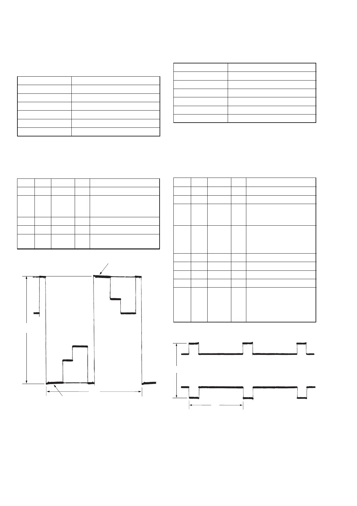
A: Amplitude of PSIG signal
Fig. 5-1-19
A: Between the reversed waveform pedestal and
non-reversed waveform pedestal
Fig. 5-1-18
Pedestal
Pedestal
A
2H
A
V
2. RGB AMP Adjustment (PD-166 board)
Set the D Range of the RGB decoder for driving the LCD to the
specified value.
If deviated, the LCD screen image will be blackish or saturated
(whitish).
Mode CAMERA
Subject Not required
Measurement Point Pin 1 of CN803 (VG)
Measuring Instrument Oscilloscope
Adjustment Page C
Adjustment Address 64
Specified Value A = 7.90 ± 0.05 Vp-p
Note 1: This adjustment is the tracking adjustment in relation to
“Black Limit Adjustment”.
Note 2: Check that the data of page: 0, address: 10 is “00”.
Adjusting method:
Order Page Address Data Procedure
1 0 01 01
2C 64
Change the data and set the
voltage (A) to the specified
value.
3 C 64 Press PAUSE button.
4 0 01 00
5
Perform “Black Limit
Adjustment”.
3. Black Limit Adjustment (PD-166 board)
Set the video signal level for driving the LCD to the specified
value.
Mode CAMERA
Subject Not required
Measurement Point Pin 6 of CN803 (PSIG)
Measuring Instrument Oscilloscope
Adjustment Page C
Adjustment Address 65
Specified Value A = 8.50 ± 0.08 Vp-p
Note 1: This adjustment is the tracking adjustment in relation to
“RGB AMP Adjustment”.
Note 2: Check that the data of page: 0, address: 10 is “00”.
Note 3: NTSC model: DCR-PC101
PAL model: DCR-PC101E
Adjusting method:
Order Page Address Data Procedure
1 0 01 01
23 C461
Set the following data
3 3 C5 5B: NTSC model
53: PAL model
4C 65
Change the data and set the
voltage (A) to the specified
value. (The data should be
“00” to “0F”)
5 C 65 Press PAUSE button.
63 C400
73 C500
8 0 01 00
9
Check that the specified
value of “RGB AMP
Adjustment” is satisfied. If
not, perform “RGB AMP
Adjustment”.