2-3
DCR-PC101/PC101E
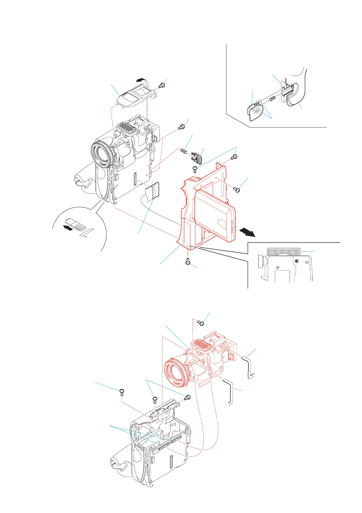
2-2. CABINET (R) BLOCK ASSEMBLY
1 Screw (M1.7)
Main frame
assembly
Battery lock
When installing the battery lock,
two claws are met and attached in a slot of the
main frame assembly.
Two claws
Cabinet (rear)
5 Two screw
(M1.7)
8 Remove the cabinet (R) block assembly
inthe direction of arrow.
qa Battery lock
0 Cabinet (R) block
assembly
9 Connector
(BJ-003 board)
(CN1003)
4 Two screw
(M1.7)
6 Screw
(M1.7)
Lens section
— Bottom view —
7 Slide the eject knob
2 Microphone cover
3 Two screws
(M1.7 × 4)
qs Compression
spring
2-3. LENS (-EVF) BLOCK SECTION
1 Flexible board (NS-014 board)
(CN104)
3 Two connectors
(CN1010, CN404)
2 Flexible board
(control switch block (PS-2850))
(CN402)
4 Two screws
(M1.7)
5 Screw (M1.7)
7 Lens (-EVF) block
section
6 Screw
(M1.7 × 4)