DCR-PC101/PC101E
5-55
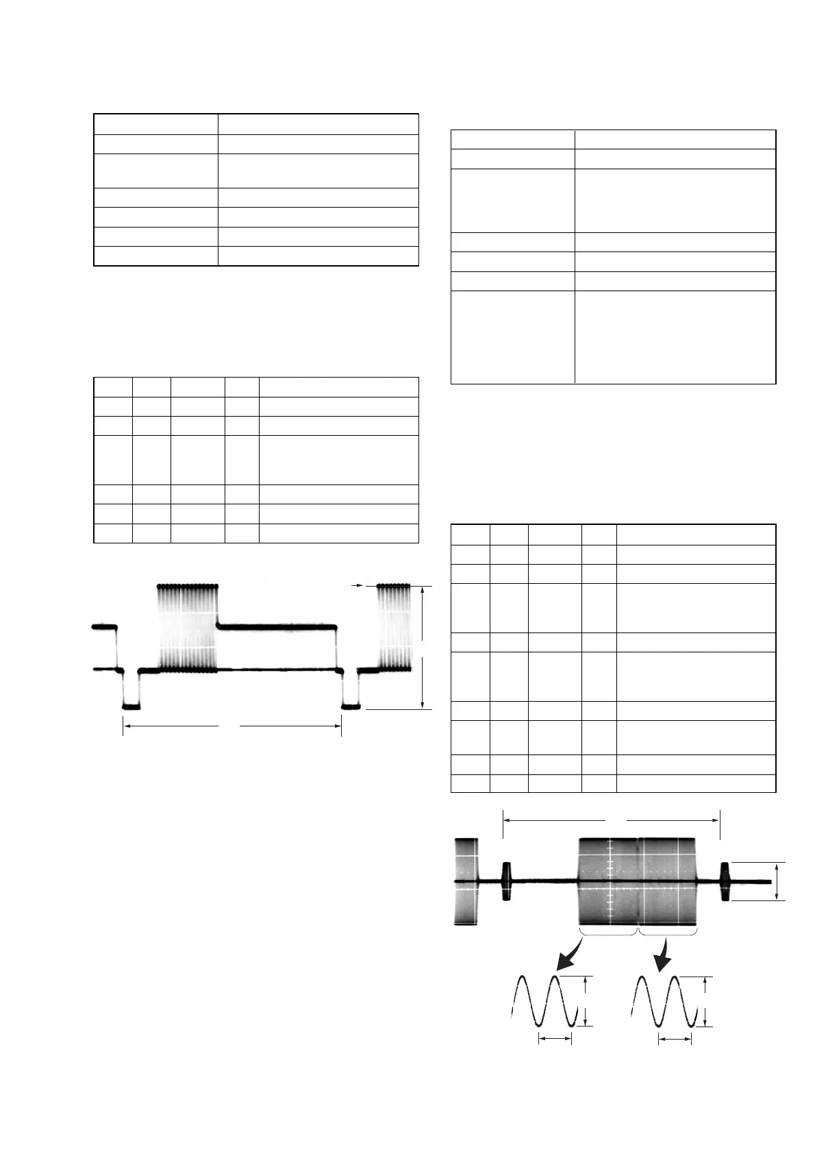
2. S VIDEO OUT Y Level Adjustment (VC-284 board)
Mode CAMERA
Subject Arbitrary
Measurement Point Y signal terminal of
S VIDEO jack (75 Ω terminated)
Measuring Instrument Oscilloscope
Adjustment Page C
Adjustment Address 25
Specified value A = 1000 ± 14 mVp-p
Note: Check that the data of page: 0, address: 10 is “00”.
Switch setting
1) DEMO MODE (Menu display) ....................................... OFF
Adjusting method:
Order Page Address Data Procedure
1 0 01 01
2 3 0C 02 Press PAUSE button.
3C 25
Change the data and set the Y
signal level (A) to the
specified value.
4 C 25 Press PAUSE button.
5 3 0C 00 Press PAUSE button.
6 0 01 00
3. S VIDEO OUT Chroma Level Adjustment
(VC-284 board)
Mode CAMERA
Subject Arbitrary
Measurement Point Chroma signal terminal of
S VIDEO jack (75 Ω terminated)
External trigger: Y signal terminal of
S VIDEO jack (75 Ω terminated)
Measuring Instrument Oscilloscope
Adjustment Page C
Adjustment Address 26, 27
Specified value
Cr level: A = 714 ± 14 mVp-p (NTSC)
A = 700 ± 14 mVp-p (PAL)
Cb level:B = 714 ± 14 mVp-p (NTSC)
B = 700 ± 14 mVp-p (PAL)
Burst level: C = 286 ± 6 mVp-p (NTSC)
C = 300 ± 6 mVp-p (PAL)
Note 1: Check that the data of page: 0, address: 10 is “00”.
Note 2: NTSC model: DCR-PC101
PAL model: DCR-PC101E
Switch setting
1) DEMO MODE (Menu display) ....................................... OFF
Adjusting method:
Order Page Address Data Procedure
1 0 01 01
2 3 0C 02 Press PAUSE button.
3C 26
Change the data and set the
Cr signal level (A) to the
specified value.
4 C 26 Press PAUSE button.
5C 27
Change the data and set the
Cb signal level (B) to the
specified value.
6 C 27 Press PAUSE button.
7
Check the burst signal (C) to
the specified value.
8 3 0C 00 Press PAUSE button.
9 0 01 00
H
Center of luminance line
A
Fig. 5-3-7
Fig. 5-3-8
H
C
A
0.28μsec (NTSC)
0.23μsec (PAL)
B
0.28μsec (NTSC)
0.23μsec (PAL)