DCR-PC101/PC101E
5-39
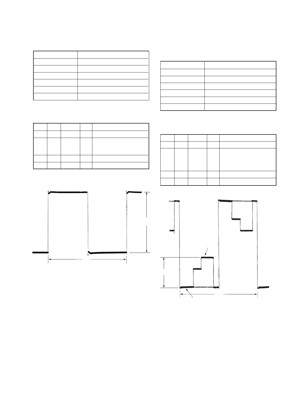
5. Contrast Adjustment (PD-166 board)
Set the video signal level for driving the LCD to the specified
value.
If deviated, the LCD screen image will be blackish or saturated
(whitish).
Mode CAMERA
Subject Not required
Measurement Point Pin 1 of CN803 (VG)
Measuring Instrument Oscilloscope
Adjustment Page C
Adjustment Address 69
Specified Value A = 2.90 ± 0.05 Vp-p
Note: Check that the data of page: 0, address: 10 is “00”.
Adjusting method:
Order Page Address Data Procedure
1 0 01 01
2C 69
Change the data and set the
voltage (A) to the specified
value. (The data should be
“00” to “7F”)
3 C 69 Press PAUSE button.
4 0 01 00
A: Amplitude of PSIG signal
Fig. 5-1-20
A
2H
4. PSIG GRAY Adjustment (PD-166 board)
Set the PSIG signal level for driving the LCD to the specified
value.
Mode CAMERA
Subject Not required
Measurement Point Pin 6 of CN803 (PSIG)
Measuring Instrument Oscilloscope
Adjustment Page C
Adjustment Address 66
Specified Value A = 5.00 ± 0.1 Vp-p
Note: Check that the data of page: 0, address: 10 is “00”.
Adjusting method:
Order Page Address Data Procedure
1 0 01 01
2C 66
Change the data and set the
voltage (A) to the specified
value.
3 C 66 Press PAUSE button.
4 0 01 00
3 steps peak
Pedestal
A
2H
A: Between the pedestal and 3 steps peak
Fig. 5-1-21